Image forming system and image forming apparatus being configured for easy removal of jammed recording material and for reducing installation space

a technology of image forming system and image forming apparatus, which is applied in the direction of electrographic process apparatus, printing, instruments, etc., can solve the problems of difficult to move the feeder unit to be apart from the side, difficult to connect the peripheral equipment of the system-up to the image forming apparatus on the side of the transport path, and limited selection of the installation space of the image forming apparatus

Active Publication Date: 2007-06-19
SHARP KK
View PDF5 Cites 5 Cited by
  • Summary
  • Abstract
  • Description
  • Claims
  • Application Information

AI Technical Summary

Benefits of technology

[0020]It is an object of the present invention to provide an image forming apparatus and an image forming system including a peripheral equipment connected to the image forming apparatus in parallel to a side wall of the main body of the image forming apparatus whi

Problems solved by technology

However, with the structure of the image forming apparatus wherein the transport path which extends in the longitudinal direction is provided on the side face of the image forming apparatus, it is difficult to connect a peripheral equipment for system-up to the image forming apparatus on the side of the transport path as in the image forming apparatuses of the Japanese Unexamined Patent Application No. 9-297440/1997 and Japanese Unexamined Patent Application No. 7-301964/1995 (Tokukaihei 7-301964).
In this case, a problem arises in that it is difficult to move the feeder unit to be apart from the side face of the image forming apparatus in an efficient manner, as the feeder unit storing a large volume recording material is very heavy.
Besides, to move the large volume feeder unit to be apart from the side face of the image forming apparatus, it is necessary to install the image forming apparatus and

Method used


Image

  • Image forming system and image forming apparatus being configured for easy removal of jammed recording material and for reducing installation space
  • Image forming system and image forming apparatus being configured for easy removal of jammed recording material and for reducing installation space
  • Image forming system and image forming apparatus being configured for easy removal of jammed recording material and for reducing installation space

Examples


first embodiment

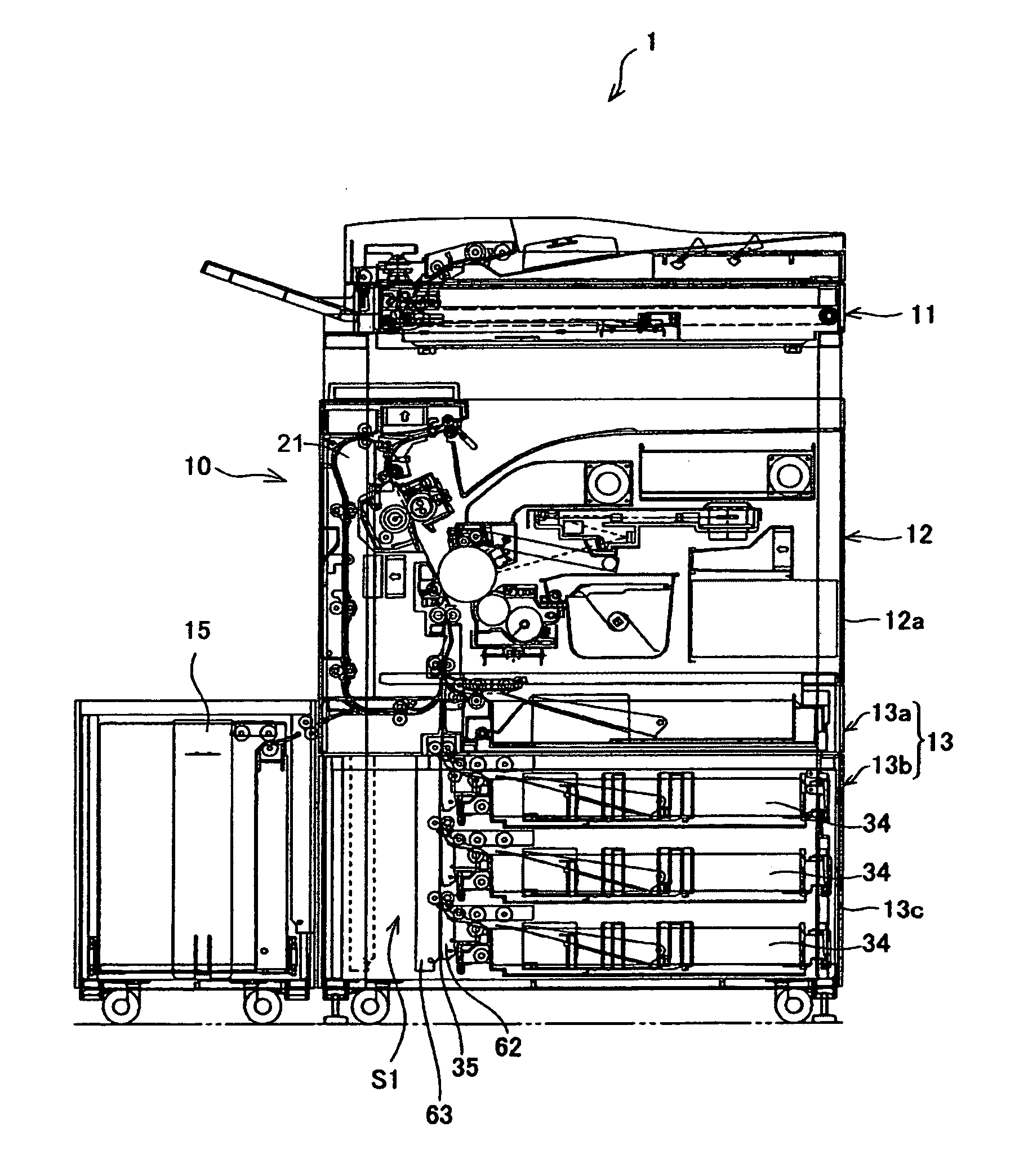
[0072]The following descriptions will explain one embodiment of the present invention in reference to FIGS. 1 to 10.

[0073]As illustrated in FIG. 1, an image forming system 1 in accordance with the present embodiment includes an image forming apparatus 10 and an external recording material supply unit (peripheral equipment) 15 connected to the image forming apparatus 10 in parallel.

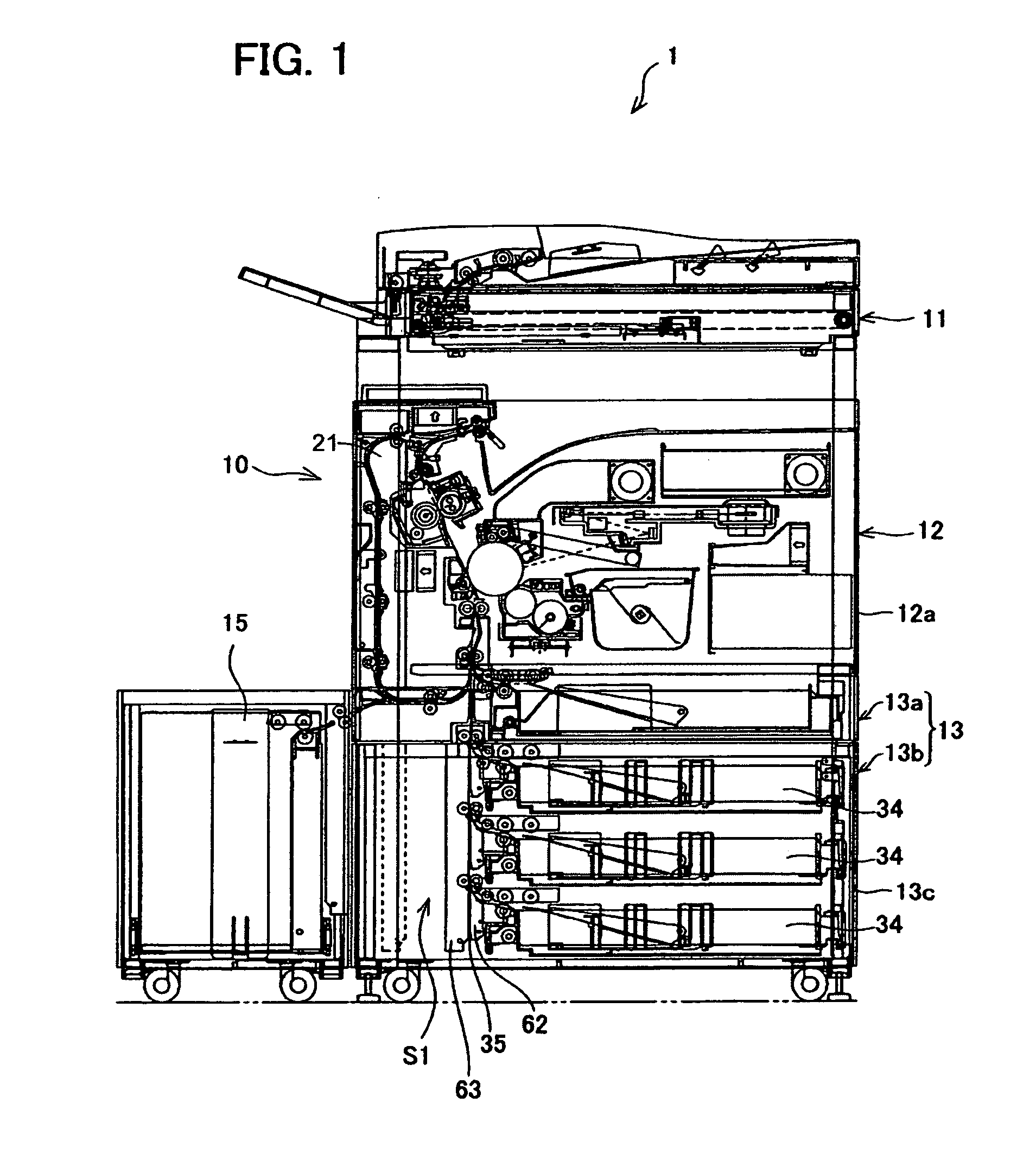
[0074]The image forming apparatus 10 includes an image recording device (image forming section) 12, and a recording material supply section 13, and forms an image on a recording material (sheet or the like) to be functioned as a copying machine, a printer, etc. The image forming apparatus 10 shown in FIG. 1 is provided with a recording material supply section 13 which is made up of a recording material supply unit 13a, and a recording material supply device (recording material storage section) 13b as an expanded unit in the image recording device main body (cabinet) 12a of the image recording device 12.

[00...


PUM


Abstract

An image forming apparatus includes an image recording device and a recording material supply device, and an external recording material supply device is connected to the recording material supply device in parallel. In a main body of the recording material supply device, a space is formed between the inner wall on a peripheral equipment connecting side and a longitudinal transport path so as to allow the longitudinal transport path to open from a front side of the recording material supply device. The longitudinal transport path is provided for transporting the recording material from the recording material supply device to the image recording device.

Description

FIELD OF THE INVENTION[0001]The present invention relates to an image forming system which permits functions to be expanded according to an environment, and an image forming apparatus adopted in such system, and more particularly relates to an image forming system wherein a copying machine, a printer or other image forming apparatus is connected to a recording material supply device or other peripheral equipment in parallel to the side face of a main body of the image forming apparatus, and an image forming apparatus to be adopted in such image forming system.BACKGROUND OF THE INVENTION[0002]In these years, image forming systems have been developed, wherein functions can be expanded by combining the image forming apparatuses with a peripheral equipment(s) as user desires or to be adjusted to the environment of use.[0003]In recent years, image forming apparatuses such as digital copying machines are more and more digitalized, and such image forming apparatuses used in offices are oft...

Claims


Application Information

Patent Timeline
IPC IPC(8): G03G21/16B41J29/00G03G15/00G03G15/23
CPCG03G15/6502G03G15/6558G03G21/16G03G2215/00367G03G2215/00544G03G2221/1675G03G15/235G03G21/1638
Inventor KIDA, HIROSHI
Owner SHARP KK
Why Eureka
Try Eureka