Vehicle power supply system

a power supply system and vehicle technology, applied in the direction of machines/engines, electric devices, process and machine control, etc., can solve the problems of reducing power supply efficiency, reducing recovery efficiency, deteriorating fuel consumption, etc., and achieve simple circuit construction of the system, ensure voltage to the important electrical load, and simplify the effect of circuit construction

Active Publication Date: 2006-05-11
DENSO CORP
View PDF11 Cites 192 Cited by
  • Summary
  • Abstract
  • Description
  • Claims
  • Application Information

AI Technical Summary

Benefits of technology

[0014] With this construction, since regenerative energy can be recovered directly to the auxiliary power source from the generator without passing through the DC / DC converter, energy recovery can be carried out efficiently. Since the main power source is charged by the auxiliary power source via the first supply circuit and the second supply circuit (i.e. it is not connected to the generator directly), for example when the generator is carrying out regeneration during deceleration of the vehicle, no large voltage fluctuations act on the main power source, and it is possible to supply power stably to the electrical loads connected to the main power source.
[0086] A vehicle power supply system according to the third aspect can be applied to a vehicle that has an automatic engine stopping / starting control device, which automatically controls stopping and restarting of the engine. With the third aspect, since engine starting can be effected more quickly, a highly beneficial effect can be obtained when the engine is restarted for example after it has been automatically stopped at, for example, an intersection.

Problems solved by technology

Firstly, regenerative energy generated by an alternator during deceleration of the vehicle is stored in the backup power storage means through the DC / DC converter.
Thus, due to the presence of the DC / DC converter between the alternator and the backup power storage means, the recovery efficiency is decreased to cause deterioration of fuel consumption.
Also, since power stored in the backup power storage means also goes through the DC / DC converter at the time of supplying electric power to the electrical loads of the vehicle, the power supply efficiency is decreased.
Thus, if the main power storage means becomes inoperable (e.g., at the time of battery death), energy recovery during deceleration becomes impossible, and also electric power cannot be supplied from the backup power storage means to the electrical loads.
Thus, the reliability of the system is largely decreased.
Firstly, since power generated by the generator is supplied to the starter battery through the DC / DC converter, energy efficiency is poor.
Thus, troubles, such as flickering of lights and wiper speed fluctuations, occur.
For example, when the power supply network battery has shorted to the ground side, it is not possible to isolate the power supply network battery and to supply power to the important devices from the starter battery.
Thus, engine starting characteristics are not improved in comparison to an ordinary 1-battery vehicle power supply system.
However, when power supply to the starter is carried out using the first battery only, it is difficult to shorten the starting time, and thus a significant advantage cannot be expected from the system set forth in U.S. Pat. No. 6,275,001 when the system is implemented in the eco-run system.

Method used


Image

  • Vehicle power supply system
  • Vehicle power supply system
  • Vehicle power supply system

Examples


first embodiment

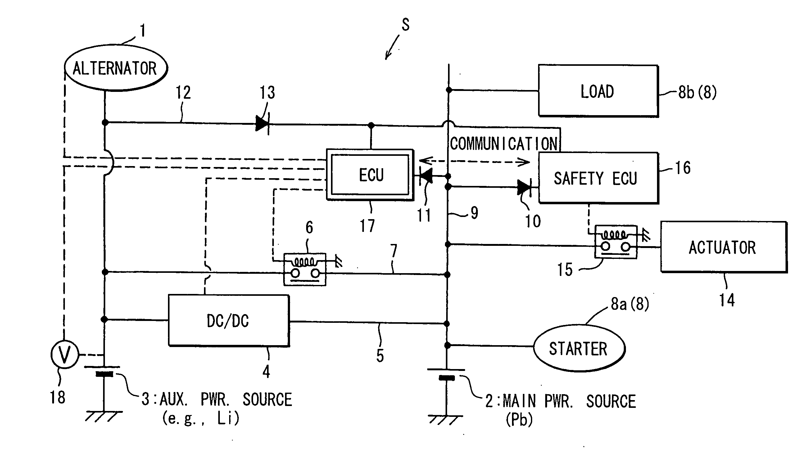
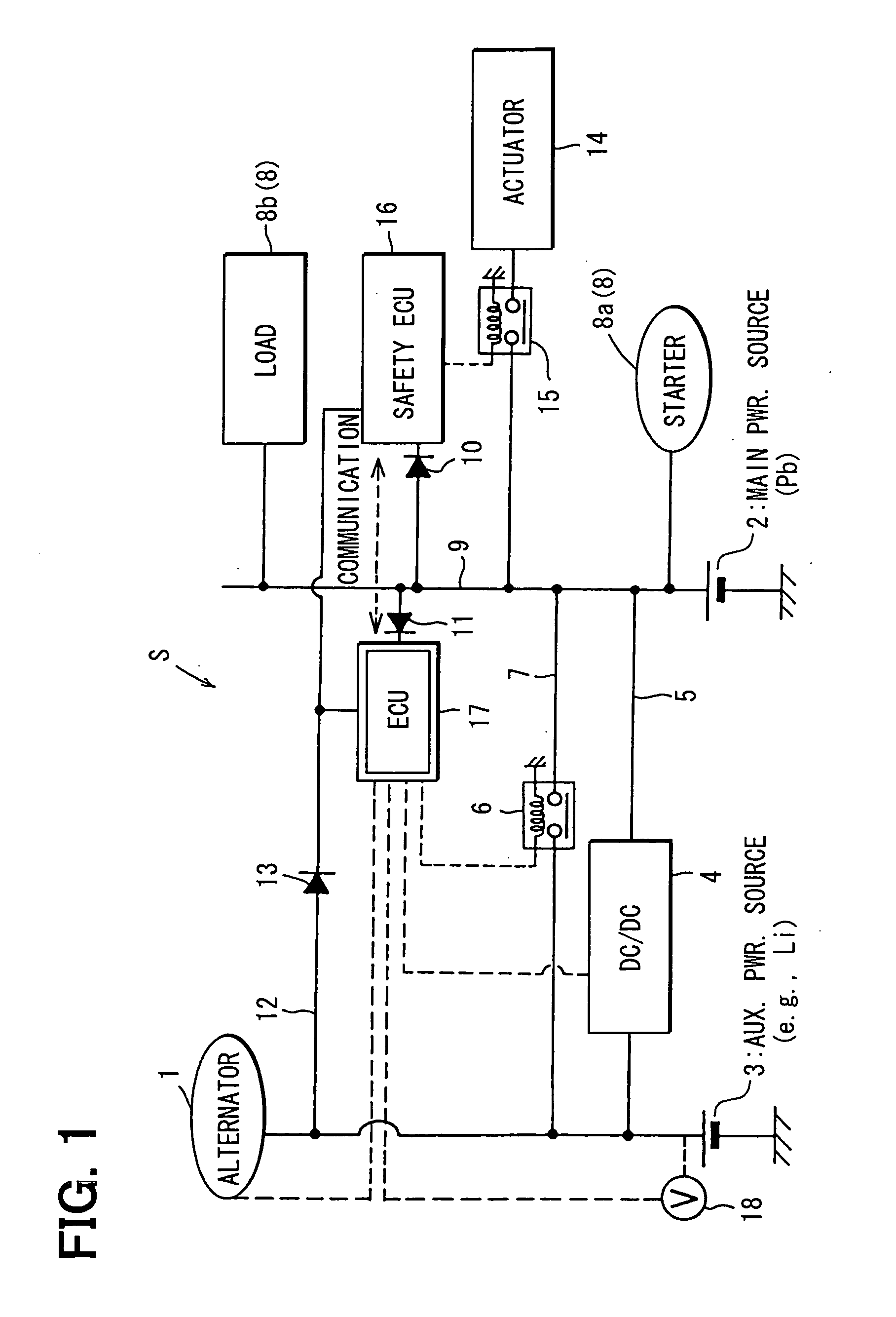
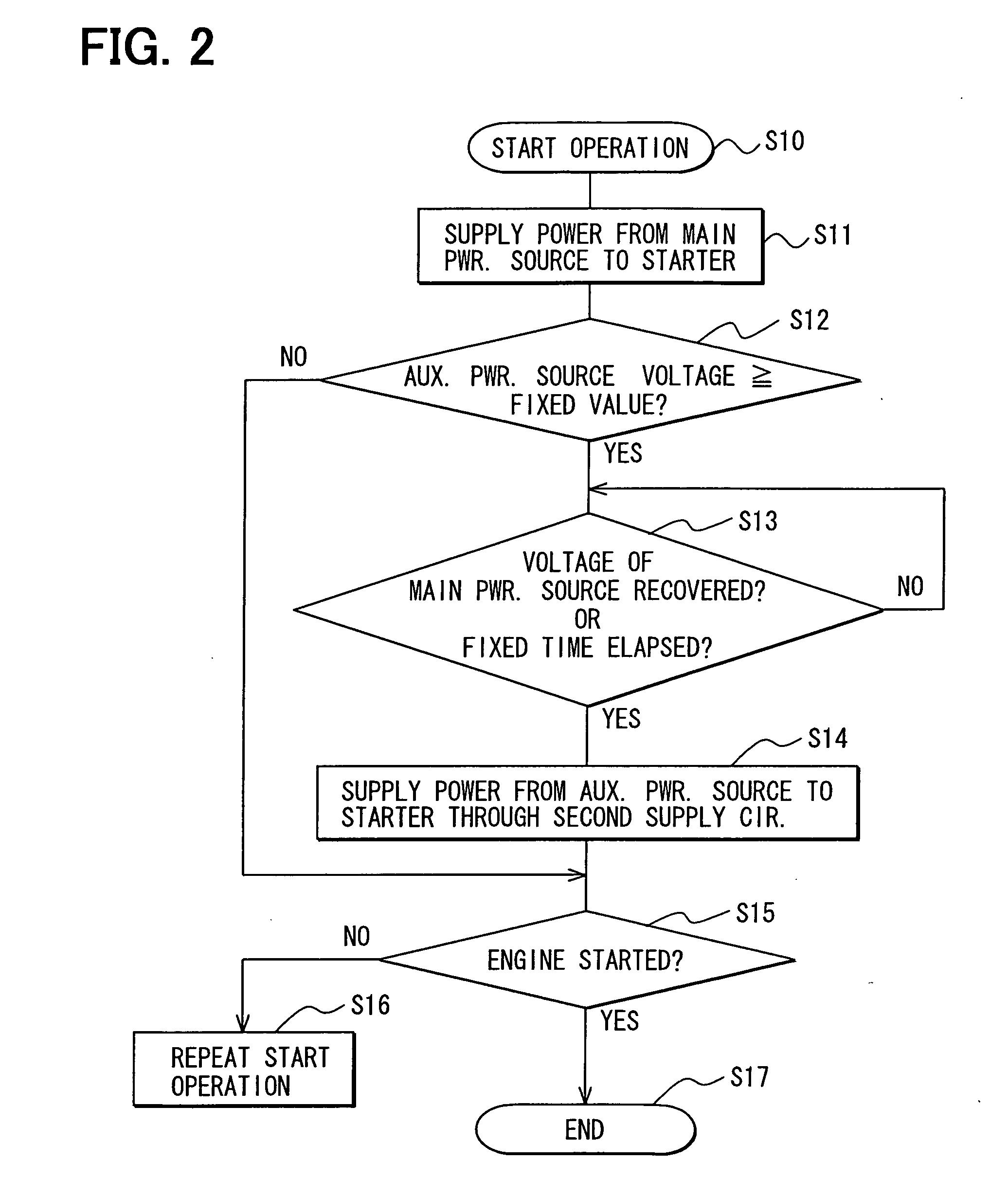
[0118]FIG. 1 is an electrical circuit diagram of a power supply system (hereinafter, referred to as a power supply system S) for an automotive vehicle according to a first embodiment. FIG. 2 is a flowchart showing a control procedure for starting an engine.

[0119] The power supply system S includes a generator 1 and two power sources (a main power source 2 and an auxiliary power source 3) and supplies electric power to electrical loads (described below) mounted on the vehicle. The generator 1 is driven by the engine (not shown).

[0120] The generator 1 is an alternator, which has an IC regulator. The generator 1 is driven by the engine through a drive belt and generates a voltage of, for example, 13 to 14 V. The generator 1 is connected directly to the auxiliary power source (sub-power source) 3 and is also connected to the main power source 2 through a power supply circuit described below.

[0121] The power supply circuit includes a first supply circuit 5 and a second supply circuit ...

second embodiment

[0137] Next, as a second embodiment, a power supply control operation for controlling supply of power from the generator 1 or the auxiliary power source 3 to the main power source 2 will be described with reference to a flowchart shown in FIG. 4. This is a method in which the charge level of the auxiliary power source 3 is sensed and is used for the power supply control operation.

[0138] At step 20, it is determined whether the output capability of the DC / DC converter 4 is greater than the total power consumption of all of the electrical loads (this will be called as an overall load value), and the charge capacity per unit time of the auxiliary power source 3 is greater than the overall load value. When the determination result is YES, control proceeds to step 21. In contrast, when the determination result is NO, control proceeds to step 22. At step 21, since there is the surplus in the charge capacity of the auxiliary power source 3 with respect to the overall load value, and there...

third embodiment

[0148] Next, as a third embodiment, a control operation of the generator 1 will be described with reference to a flowchart shown in FIG. 5. In this method, the control operation is carried out based on the power source voltages only without using a sensing means of an SOC.

[0149] At step 40, it is determined whether the output voltage V1 of the auxiliary power source 3 is equal to or above a fixed value (e.g., 12 V). When the determination result is YES, control proceeds to step 41. In contrast, when the determination result is NO, control proceeds to step 42. At step 41, since there is the surplus in the charge capacity of the auxiliary power source 3, power generation by the generator 1 is cut off, and electric power is supplied from the auxiliary power source 3 to the main power source 2 through the first supply circuit 5 (the DC / DC converter 4) (first control state).

[0150] At step 42, it is determined whether the vehicle is decelerating, and furthermore the output voltage V1 of...


PUM


Abstract

A main power source (2) is, for example, an ordinary Pb battery and generates a voltage of 12-13 V. At the time of starting an engine, the main power source (2) supplies power to a starter (8a). The main power source (2) is given a higher priority than an auxiliary power source (3) to supply power to ordinary loads (8b). The auxiliary power source (3) is a high performance battery (e.g., Li ion battery), which has superior charge acceptance capability and better state detectability over the main power source (2). Furthermore, the auxiliary power source (3) has an internal resistance per unit capacity, which is smaller than that of the main power source (2), and generates a voltage of 9-12 V. A generator (1) is directly connected to the auxiliary power source (3). The auxiliary power source (3) stores regenerative power, which is generated by the generator (1) at the time of deceleration of a vehicle, and is used as a redundant power source for the main power source (2). The main power source (2) and the auxiliary power source (3) are connected to each other through a supply circuit (5), which has a DC / DC converter (4), and a second supply circuit 7, which has a switch (6).

Description

TECHNICAL FIELD [0001] The invention relates to a vehicle power supply system having two batteries (a main power source and an auxiliary power source). BACKGROUND ART [0002] A previously proposed vehicle power supply system having two batteries (2-battery system) is disclosed in, for example, JP-A-6-296332, JP-A-2001-186687 or U.S. Pat. No. 6,275,001. [0003] The system set forth in JP-A-6-296332 includes a main power storage means and a backup power storage means, which are connected to each other through a DC / DC converter. Switching of the DC / DC converter is controlled in such a manner that regenerative energy (electric power), which is obtained during deceleration of the vehicle, is stored in the backup power storage means, and the stored electric power is supplied from the backup power storage means to the electrical loads of the vehicle at time (e.g., time of accelerating the vehicle, time of steady driving of the vehicle or time of idling the engine) other than the time of dece...

Claims


Application Information

Patent Timeline
Patent Type & Authority Applications(United States)
IPC IPC(8): B60L1/00B60L50/15B60R16/02B60R16/03H02J7/14
CPCB60R16/03F02N11/0866F02N2200/063F02N2250/02H02J7/1423Y02T10/7005H02J2310/46Y02T10/70
Inventor KATO, AKIRATANAKA, KATSUNORIKAMIYA, MASARUSENDA, TAKASHI
Owner DENSO CORP
Why Eureka
Try Eureka