Combo-type male and female universal series bus connector
- Summary
- Abstract
- Description
- Claims
- Application Information
AI Technical Summary
Problems solved by technology
Method used
Image
Examples
first embodiment
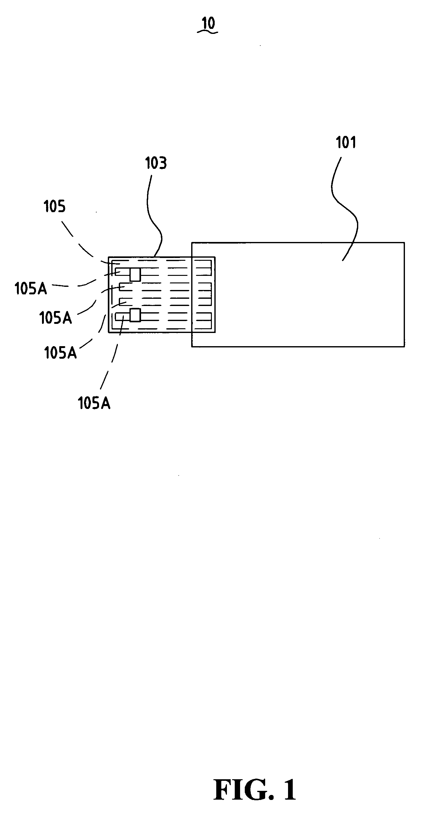
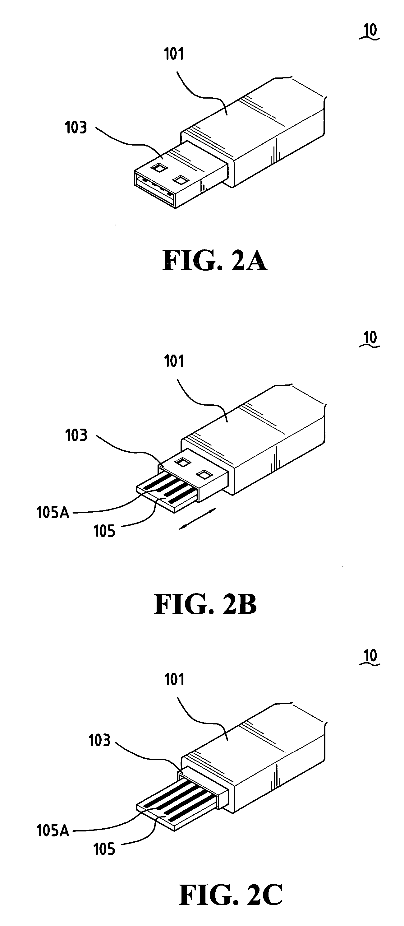
[0026]FIGS. 2A, 2B and 2C show the USB connector according to the present invention. FIG. 2A illustrates the USB connector 10 acts as the female USB connector. FIG. 2B illustrates the metallic shell 103 is movable and has been moved toward inside the wrap piece 101 against an elastic force provided by an elastic device (not shown) in the wrap piece 101. FIG. 3C illustrates the metallic shell 103 enters inside wrap piece 101 to expose the electrically connecting terminals 105A on the electrically connecting terminal board 105 such that the USB connector 10 then acts as a male USB connector.
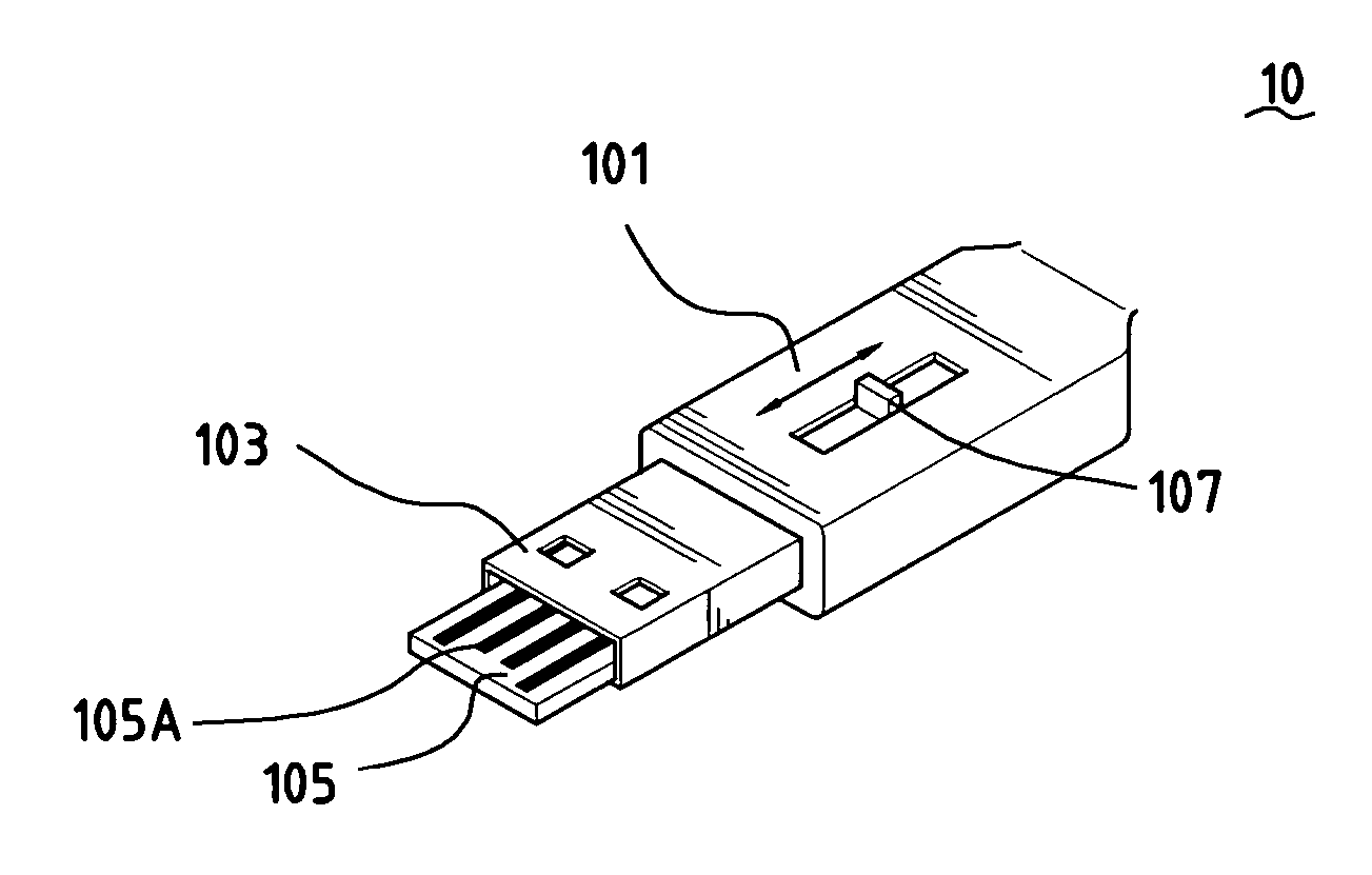
[0027]FIGS. 3A, 3B and 3C show the second embodiment of the USB connector according to the present invention The USB connector 10 in the second embodiment provides a sliding piece 107 which is placed in a guide groove at a sidewall of the wrap piece 101 for moving the metallic shell 105. FIG. 3A illustrates the USB connector 10 acts as the female USB connector. FIG. 3a illustrates the metallic shel...
third embodiment
[0028]FIGS. 4A, 4B and 4C show the USB connector according to the present invention. The USB connector 10 further provides a sliding piece 107 which is placed in a guide groove at the top wall of wrap piece 101 or the bottom wall of the wrap piece 101 (not shown) for moving the electrically connecting terminal board 105. FIG. 4A illustrates the USB connector 10 acts as a female-type USB connector. FIG. 4B illustrates the electrically connecting terminal board is movable once the sliding piece 107 is moved along the guide groove. FIG. 4C illustrates the electrically connecting terminal board 105 is moved outward the metallic shell 103 to expose the electrically connecting terminals 105A such that the USB connector 10 then acts as a male USB connector.
fourth embodiment
[0029]FIGS. 5A, 5B and 5C show the USB connector according to the present invention. FIG. 5A illustrates the USB connector 10 acts as the female USB connector. The metallic shell 103 is composed of two metallic shell halves and the second end of one of the metallic shell halves is pivotally connected to the front end of the wrap piece 101 with a recess at the front end of the wrap piece 101 corresponding to the metallic shell half FIG. 5B illustrates the metallic shell half is rotationally movable with respect to the front end of the wrap piece 101. FIG. 5C illustrates the metallic shell half is moved to a position perpendicular to the electrically connecting terminal board 105 with the second end thereof being disposed in the recess at the front end of the wrap piece 101 to expose the electrically connecting terminal 105A on the electrically connecting terminal board 105 completely such that the USB connector 10 then acts as the nude USB connector.
PUM
 Abstract
Description
Claims
Application Information
 - R&D
- Intellectual Property
- Life Sciences
- Materials
- Tech Scout
- Unparalleled Data Quality
- Higher Quality Content
- 60% Fewer Hallucinations
Browse by: Latest US Patents, China's latest patents, Technical Efficacy Thesaurus, Application Domain, Technology Topic, Popular Technical Reports.
© 2025 PatSnap. All rights reserved.Legal|Privacy policy|Modern Slavery Act Transparency Statement|Sitemap|About US| Contact US: help@patsnap.com


