Intake air amount control apparatus and intake air amount control method for internal combustion engine

Inactive Publication Date: 2006-08-03
TOYOTA JIDOSHA KK
View PDF3 Cites 16 Cited by
  • Summary
  • Abstract
  • Description
  • Claims
  • Application Information

AI Technical Summary

Benefits of technology

[0005] Accordingly, it is an objective of the present invention to provide an intake air amount control apparatus of an internal combustion engine that is equipped with changing mechanisms that change the manner in which intake air is supplied to the internal combustion engine, and to r

Problems solved by technology

However, with the intake air amount control apparatus that executes such a cooperative control, the following disadvantages may occur.
That is, when the operational response of a changing mechanism other than the variable valve lift mechanism is reduced for some reason, the variable valve lift mechanism may be driven assuming that the operational response has not been reduced, or the variable valve lif

Method used


Image

  • Intake air amount control apparatus and intake air amount control method for internal combustion engine
  • Intake air amount control apparatus and intake air amount control method for internal combustion engine
  • Intake air amount control apparatus and intake air amount control method for internal combustion engine

Examples


Example

[0015] One embodiment of the present invention will now be described with reference to FIGS. 1 to 3.

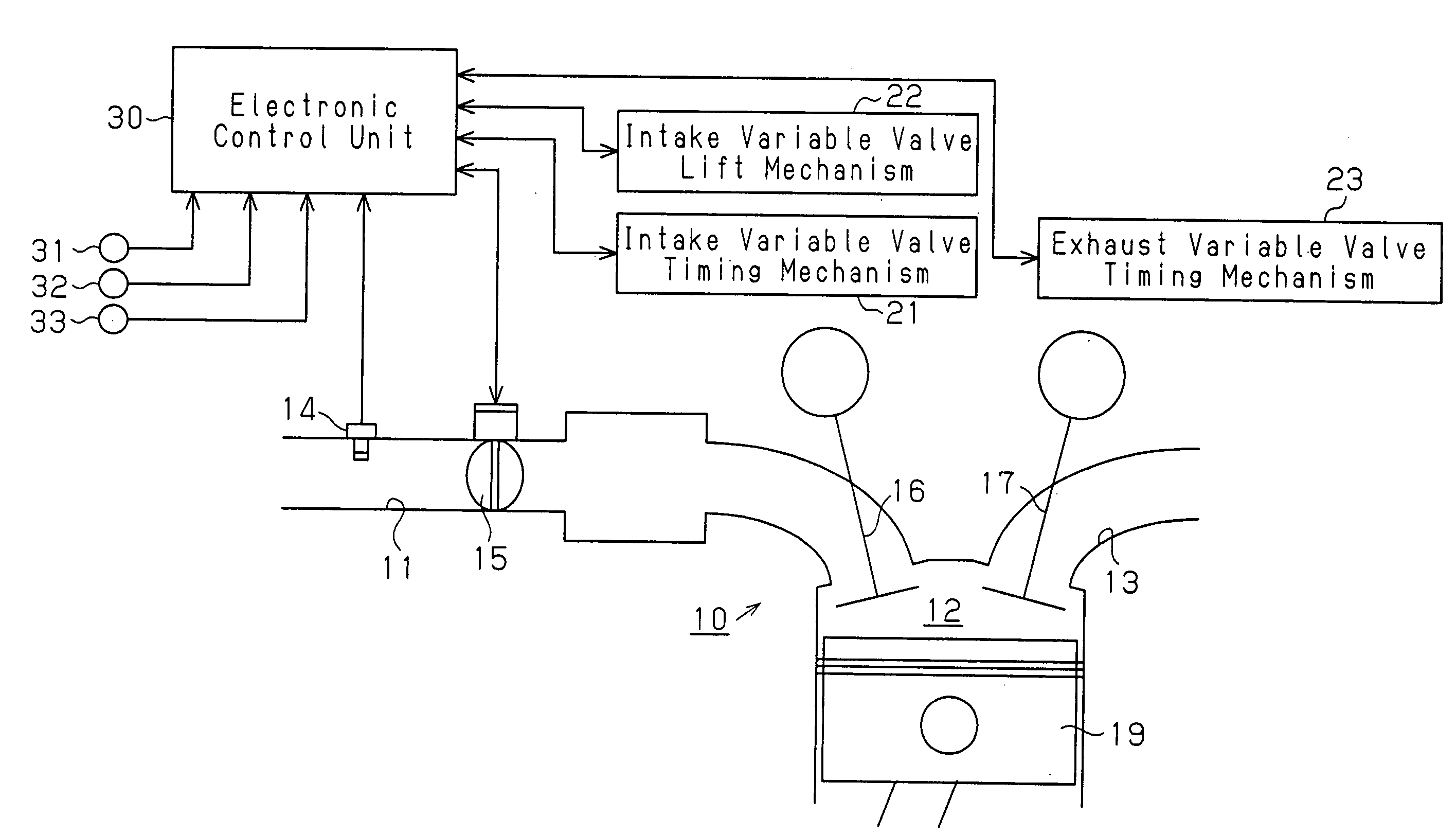
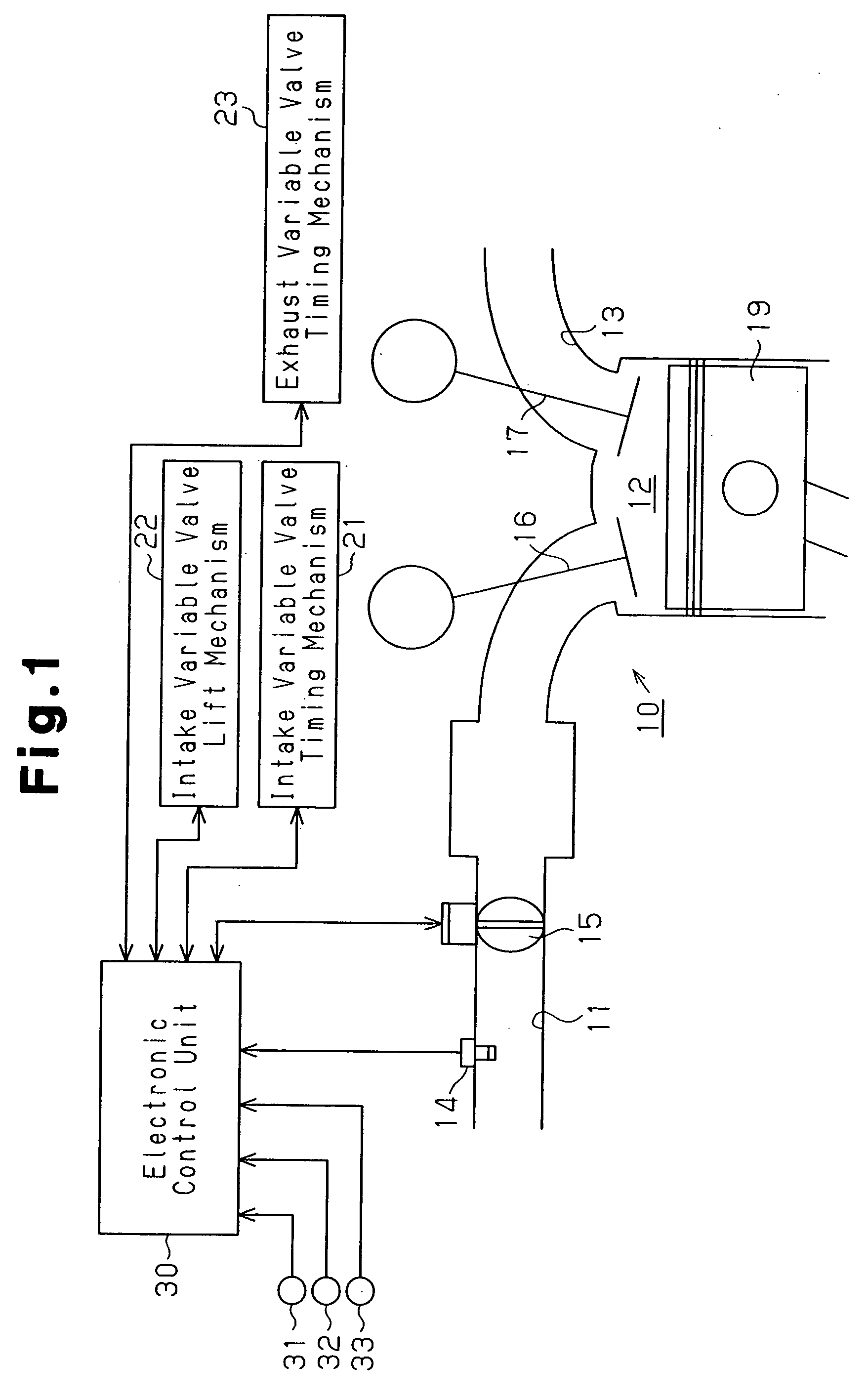
[0016]FIG. 1 shows a schematic configuration of a vehicle internal combustion engine 10 according to the preferred embodiment. As shown in FIG. 1, the internal combustion engine 10 is generally configured by an intake passage 11, combustion chambers 12 (only one is shown), and an exhaust passage 13.

[0017] Specifically, the engine 10 also has cylinders, in each of which one of the combustion chambers 12 is defined. The engine 10 also has fuel injection valves, ignition plugs, intake valves 16, and exhaust valves 17, each corresponding to one of the combustion chambers 12. In the following, only one set of a combustion chamber 12, an injection valve, an ignition plug, an intake valve 16, and an exhaust valve 17 will mainly be discussed as representing all the combustion chambers 12, the injection valves, the ignition plugs, the intake valves 16, and the exhaust valves 17.

[0018] The i...


PUM


Abstract

A plurality of changing mechanisms change the manner in which intake air is supplied to an internal combustion engine. A control unit executes a cooperative control in which, based on the driving state of one of a variable vale lift mechanism and at least one of the other changing mechanisms other than the variable valve lift mechanism, the driving state of the other one of the variable valve lift mechanism and the at least one of the changing mechanisms is controlled. A determining unit determines whether the operational response of the changing mechanisms is decreased. A restricting unit restricts the cooperative control when the determining unit determines that the operational response of at least one of the changing mechanisms is decreased. Therefore, disadvantages caused by reduction in the operational response of the changing mechanisms are reduced.

Description

BACKGROUND OF THE INVENTION [0001] The present invention relates to an intake air amount control apparatus for an internal combustion engine that is equipped with changing mechanisms that change the manner in which intake air is supplied to the internal combustion engine. The present invention also pertains to an intake air amount control method for the internal combustion engine. [0002] In the internal combustion engine, the intake air amount is generally regulated by selectively opening and closing a throttle valve and is controlled in accordance with the operating state of the engine. Also known is an intake air amount control apparatus that changes the valve timing of intake valves (also the valve timing of exhaust valves in some cases) in addition to the throttle valve (for example, Japanese Laid-Open Patent Publication No. 2003-314308). An internal combustion engine has also been proposed that is equipped with a variable valve lift mechanism that changes the maximum lift of th...

Claims


Application Information

Patent Timeline
IPC IPC(8): F01L1/34
CPCF01L1/34F01L13/0015F01L2001/0537F01L2001/34496F01L2800/00F02D13/0207F02D13/0253F02D41/0002F02D2041/001Y02T10/42Y02T10/18Y02T10/12Y02T10/40
Inventor FUWA, NAOHIDE
Owner TOYOTA JIDOSHA KK
Why Eureka
Try Eureka