Decorative candle having an embedded design

a candle and design technology, applied in the field of candles, can solve the problems of creating the most interesting shadows, consuming design and melting the wax supporting the decorative elements as the candle burns

Inactive Publication Date: 2006-08-03
HOHERTZ RODNEY
View PDF26 Cites 13 Cited by
  • Summary
  • Abstract
  • Description
  • Claims
  • Application Information

AI Technical Summary

Benefits of technology

[0010] The present invention provides a decorative candle having a wick extending along a wick axis for a distance equal to a wick length. A decorative design structure is spaced radially apart from, and extending along, the wick axis for a distance greater than half the wick length, wherein the decorative design structure is self-supporting on a bottom surface. Portions of the decorative design structure are located over an angle of greater than 180 degrees with respect to the wick axis. A translucent candle body material has a geometric shape that extends from the candle base along a portion of the wick axis, and surrounds a portion of the wick and the decorative design structure. The geometric shape of the candle body extends radially from the wick axis to an outer candle surface that is radially beyond the decorative design structure. The design may be cut from flat metal stock and formed into a structure.

Problems solved by technology

Many times the design on the outside of a candle is made of candle wax, which means that the design may be consumed as the candle burns.
A disadvantage of suspending design elements in wax surrounding the candle core is that the wax that supports the decorative elements may melt down as the candle is consumed.
If this happens, the flame will cast light over the decorative elements rather than shining through the decorative elements, which does not create the most interesting shadows.
Additionally, candles made with decorative elements in an outer layer usually require more time, effort, and expense to manufacture because the candle body is formed using a more complex process.

Method used


Image

  • Decorative candle having an embedded design
  • Decorative candle having an embedded design
  • Decorative candle having an embedded design

Examples


Embodiment Construction

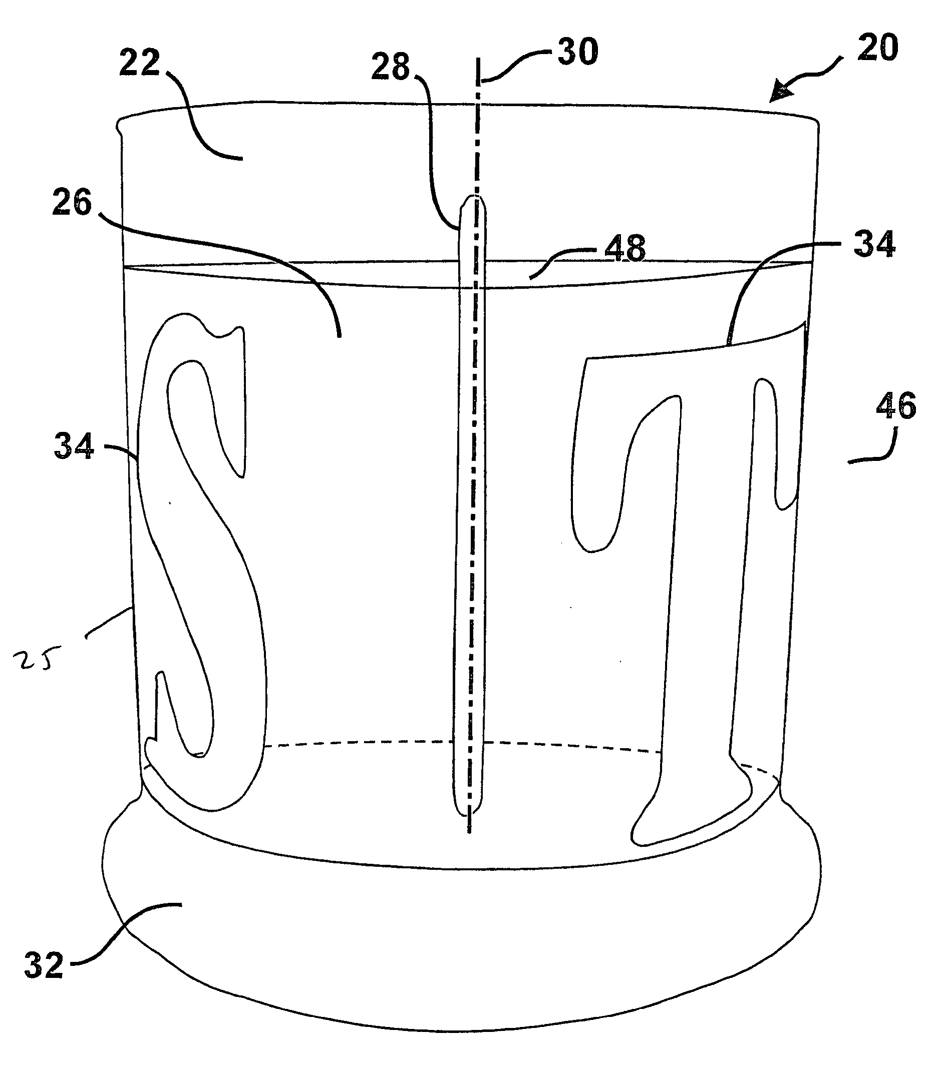
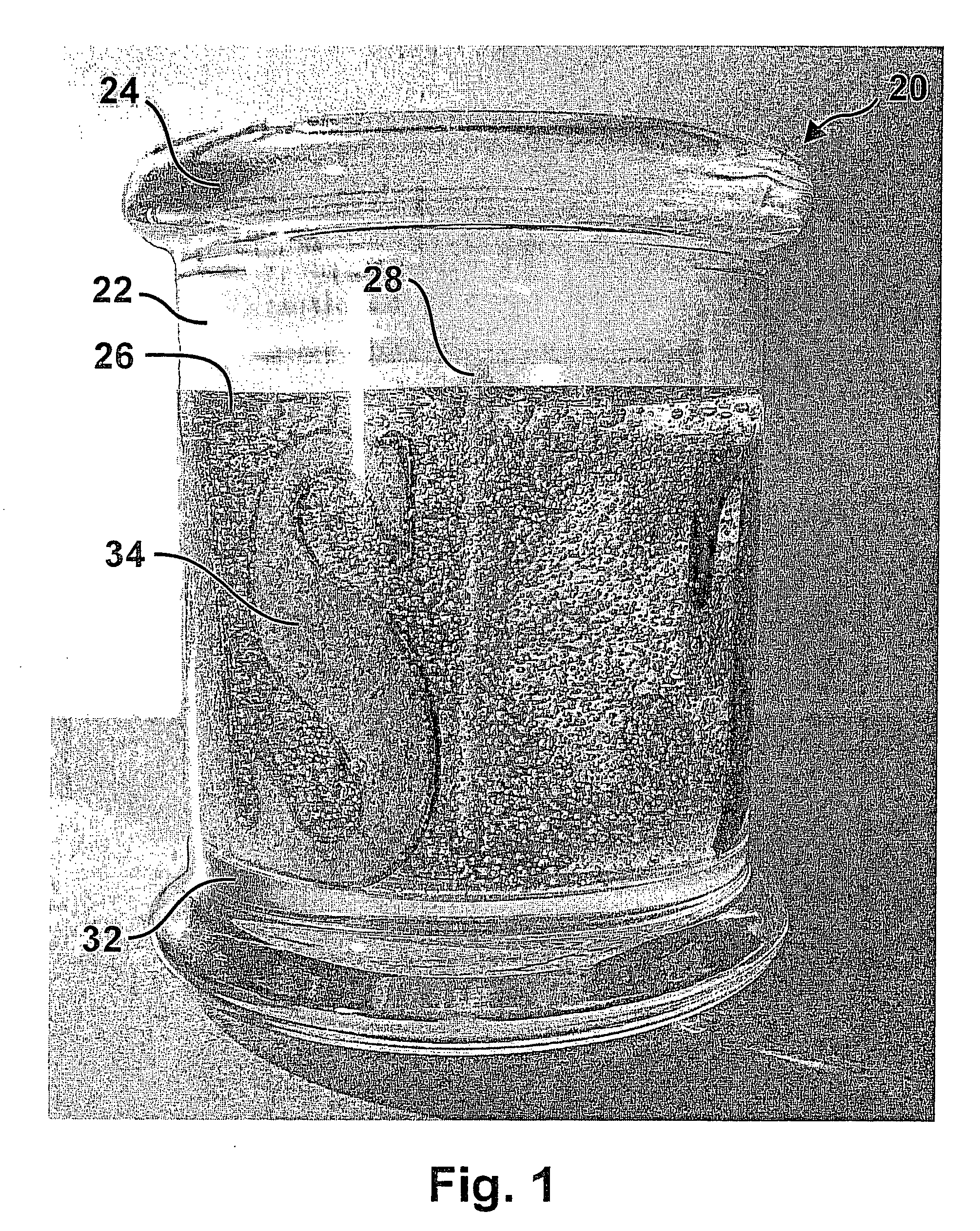
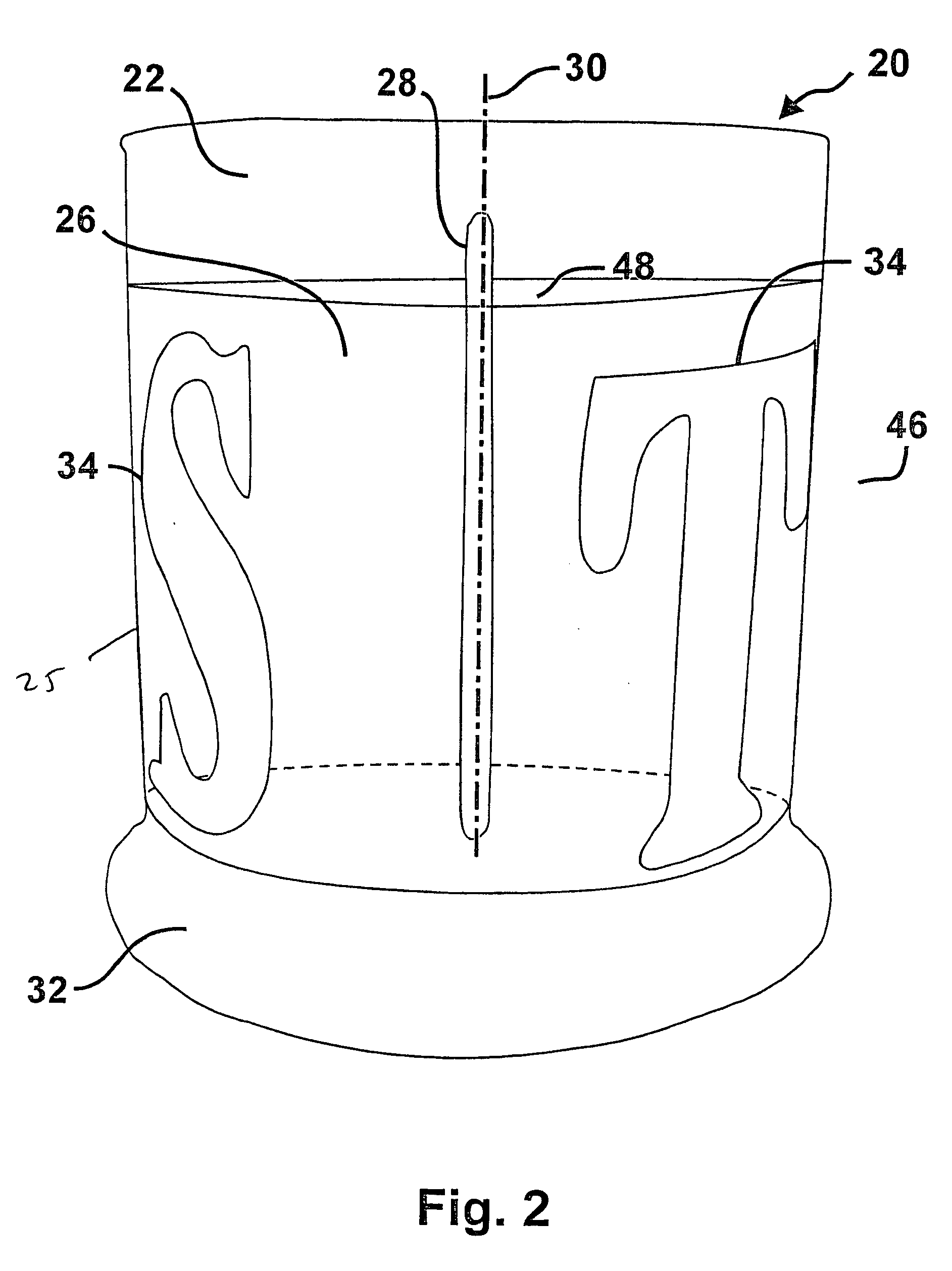
[0019] With reference now to the drawings, and in particular with reference to FIGS. 1 and 2, there is depicted decorative candle 20 in accordance with the method and apparatus of the present invention. As shown, decorative candle 20 includes candle container 22, which in the preferred embodiment shown is a glass jar having a glass lid 24. A portion of the candle container is filled with transparent candle body material 26. The candle 20 includes decorative design structure 34 embedded in the candle body material 26. Candle body material 26 is preferably transparent, but may be translucent, which means that it is almost transparent, allowing light to pass through diffusely. Candle body material 26 may also be tinted with an aesthetically pleasing colorant, and may include bubbles dispersed throughout the material, as shown in FIGS. 1 and 4A. The suspended gas or air bubbles may be introduced to further reflect or refract light from a candle flame. It is an important aspect of the pr...


PUM


Abstract

A decorative candle includes a wick extending along a wick axis for a distance equal to a wick length. A decorative design structure is spaced radially apart from, and extending along, the wick axis for a distance greater than half the wick length, wherein the decorative design structure is self-supporting on a bottom surface. Portions of the decorative design structure are located over an angle of greater than 180 degrees with respect to the wick axis. A translucent candle body material has a geometric shape that extends from the candle base along a portion of the wick axis, and surrounds a portion of the wick and the decorative design structure. The geometric shape of the candle body extends radially from the wick axis to an outer candle surface that is radially beyond the decorative design structure. The design may be cut from flat metal stock and formed into a structure.

Description

BACKGROUND OF THE INVENTION [0001] 1. Field of the Invention [0002] The present invention relates generally to candles, and more particularly to translucent candles having embedded ornamental features or designs. [0003] 2. Description of the Prior Art [0004] There are many ways for decorating and otherwise enhancing the beauty of a candle. For example, candles are frequently placed in containers having designs that are made into the container, or applied to the container, so that candlelight can be seen flickering through openings or transparent portions of the design. When the candle shines through the design, the candlelight may cast a pleasing, decorative shadow on a nearby wall or other surface. As the candle burns and is consumed, the decorative design on the container will remain rigid and supported while the flame descends along the wick, moving into the decorative container as the candle burns away. Shadows of candlelight are more beautiful and produced at more angles from t...

Claims


Application Information

Patent Timeline
Patent Type & Authority Applications(United States)
IPC IPC(8): F23D3/16
CPCC11C5/008F21V35/00
Inventor HOHERTZ, RODNEY
Owner HOHERTZ RODNEY
Why Eureka
Try Eureka