Boiler wall tube welding tool

a welding tool and boiler wall technology, applied in the direction of manufacturing tools, soldering devices, auxilary welding devices, etc., can solve the problems of occlude the viewing area, and achieve the effect of facilitating visual observation of adjacent ends

Inactive Publication Date: 2006-09-07
HOLLOWAY SCOTT
View PDF10 Cites 10 Cited by
  • Summary
  • Abstract
  • Description
  • Claims
  • Application Information

AI Technical Summary

Benefits of technology

[0007] The kind of boiler wall that is of concern here comprises a parallel array of boiler wall tubes wherein adjacent surfaces of adjacent tubes are joined by webs; moreover, the spacings between adjacent tubes are narrow. Consequently, there is very limited space for a welder to view a weld site so that it is important that any welding tool that is used to clamp into alignment tubes that are to be joined by welding not excessively occlude the available viewing area. The present invention provides a boiler wall tube welding tool that includes a base and a pair of ...

Problems solved by technology

Consequently, there is very limited space for a welder to view a weld site so that it is important that any welding tool ...

Method used


Image

  • Boiler wall tube welding tool
  • Boiler wall tube welding tool
  • Boiler wall tube welding tool

Examples


Embodiment Construction

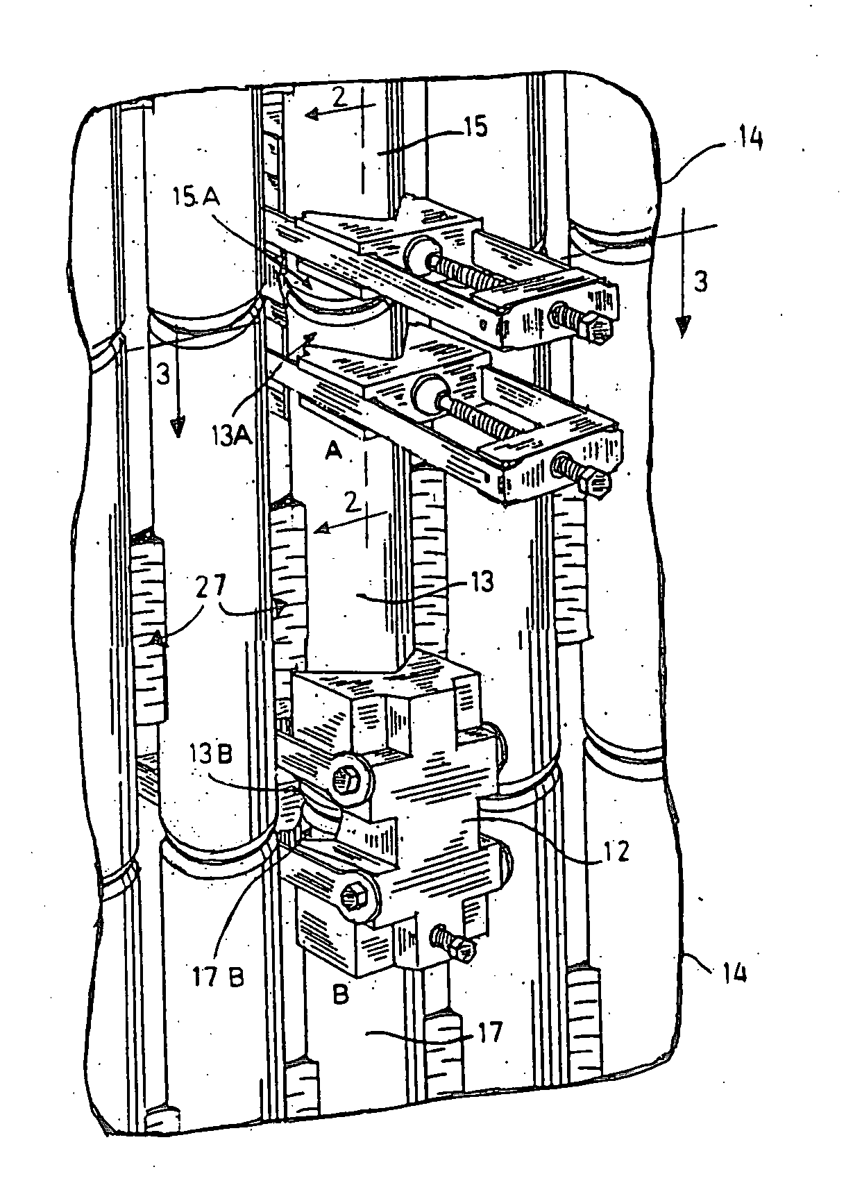
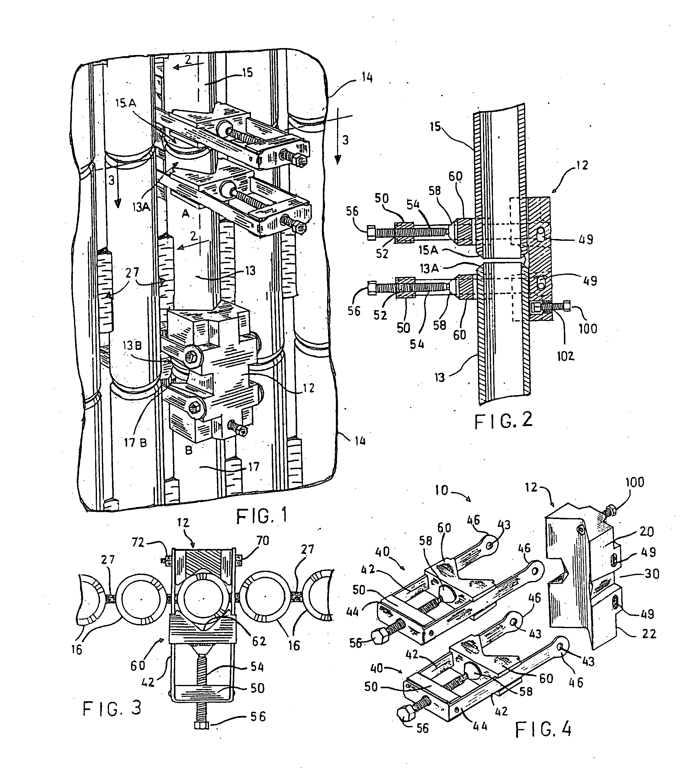
[0019] Without limiting the scope of the invention, the preferred features of this invention will be described. In FIGS. 1-3, a boiler wall 14 is depicted in fragmentary, perspective view and comprises a plurality of laterally spaced tubes 16 that are closely spaced together and connected by webs 27. We will suppose that a deteriorated segment of one of the tubes 16 has been severed and removed, leaving in place an upper tube segment 15 and a lower tube segment 17, and a welder is proceeding to replace the missing tube segment with a new tube segment 13. Two of the boiler wall tube tools 10 are depicted in FIG. 1, an upper tool 10 denoted by A and a lower tool 10 denoted by B. The upper tool A is being used to clampingly secure in alignment the ends 13A and 15A of tube segments 13 and 15, respectively; similarly, the lower tool 10 denoted by B is used to clampingly secure in alignment the ends 13B and 17B of pipe segments 13 and 17, respectively. Once welded, the tube segments 13, 1...


PUM


Abstract

A boiler wall tube tool for clamping together for welding adjacent ends of boiler wall tube segments in a boiler wall having narrowly spaced apart tubes. The tool includes a base with a tube engaging recess, and a pair of clamp members that attach to the base. The base has cutouts and notches to facilitate a welder's observation of the welding process. Each of the pipe clamp members includes a parallel pair of guides that are insertable between adjacent tubes of a boiler wall and are attachable by nuts and bolts to opposite sides of the base. A header that joins the guides has a threaded bore. A saddle block mounted for sliding movement between the guides is attached by a swivel nut to a clamp screw that is mounted within the threaded bore. Each saddle block is recessed for engaging an exterior surface of one of two aligned tube segments. The tool clamps aligned segments together by rotation of the clamp screws in a first direction; rotation of the screws in an opposite direction permits detaching the tool from the pipe segments. A lateral adjustment screw is provided for adjusting the tool for snug fit to adjacent, aligned tube segments.

Description

CROSS REFERENCE TO RELATED Applications [0001] None. STATEMENT REGARDING GOVERNMENT SPONSORED RESEARCH [0002] None BACKGROUND OF THE INVENTION [0003] 1. Field of the Invention [0004] This invention relates to a tool for clamping the ends of boiler wall tubes in alignment so that the ends of the tubes may be welded together. More particularly, the present invention relates to a boiler wall tube welding tool designed for use in boiler tube walls having closely spaced, laterally adjacent tubes joined by a web. [0005] 2. Background Art [0006] Boiler walls comprise a parallel array of tubes through which water circulates. Over time, the tubes degrade and must be replaced. Replacement proceeds by cutting out a portion of the wall that contains the tube segments that need replacing, followed by aligning, clamping, and welding new tube segments to the severed ends of the tubes. The remainder of the cut out portion of the wall is then restored. Various tools for clamping the ends of tubes in...

Claims


Application Information

Patent Timeline
IPC IPC(8): B23P15/26
CPCB23K37/0533Y10T29/53113B23K2201/06B23K2101/06
Inventor HOLLOWAY, SCOTT
Owner HOLLOWAY SCOTT
Why Eureka
Try Eureka