Personalized air conditioning/ displacement ventilation system

Inactive Publication Date: 2006-09-21
LEVY HANS F +1
View PDF26 Cites 13 Cited by
  • Summary
  • Abstract
  • Description
  • Claims
  • Application Information

AI Technical Summary

Benefits of technology

[0030] Consequently, in the field of heating and cooling there exists a need for providing a flow of conditioned air directly to or near a person sitting at a workstation, without blowing at the person and without creating a draft, as well as to occupants of the surrounding area. More particularly, there exists a need for a workstation to be so equipped wherein the occupant can individually control and obtain the amount of conditioned air supplied within the workstation while maintaining a desirable flow of conditioned air to surrounding areas. The amount of conditioned air within the workstation is controlled by the person to maximize the comfort level, well being health and level of productivity of each worker, while maintaining a desirable flow of conditioned air to surrounding areas.
[0031] Conventional room dividers for workstations may supply conditioned air to workstations, which conditioned air flows through an air flow grille at about the height where the worker is seated but the worker has very little control over the flow of the air or its direction. Such room dividers consist of a hollow space being created by panels that are spaced from each other by a predetermined distance to define an air flow there between. The hollow room divider is placed on an opening in the floor which floor is spaced above the slab of the building which constitutes the building floor to thereby form a large or major air plenum. This air plenum, therefore, is formed by the slab of the building floor and the raised floor being spaced above the slab of the building. The air plenum is charged with conditioned air (hot or cold) at or near room pressure to be explained below. Applicants' prior art U.S. Pat. Nos. 4,646,966; 4,860,642; 5,135,436; 6,238,462 and 6,318,113 are directed to conditioned air being supplied through a floor plenum and from there distributed to individual workstations through various forms of air delivery. This system differs from others by pre

Problems solved by technology

In a building whether large or small, for example, the control of temperature, air flow, humidity and the like, or even individual rooms and workstations leaves many persons in the building or within a room or in the vicinity of a workstation uncomfortable or dissatisfied with the condition of their particular environment.
Also, different locations in a building or on a floor, or even a single room or closer yet in the vicinity of a workstation, are not satisfactorily heated or cooled, that is, air conditioned, and give rise to complaints about discomfort and illness, resulting in absenteeism, sickness and, of course, loss of productivity.
Further,

Method used


Image

  • Personalized air conditioning/ displacement ventilation system
  • Personalized air conditioning/ displacement ventilation system
  • Personalized air conditioning/ displacement ventilation system

Examples


Example

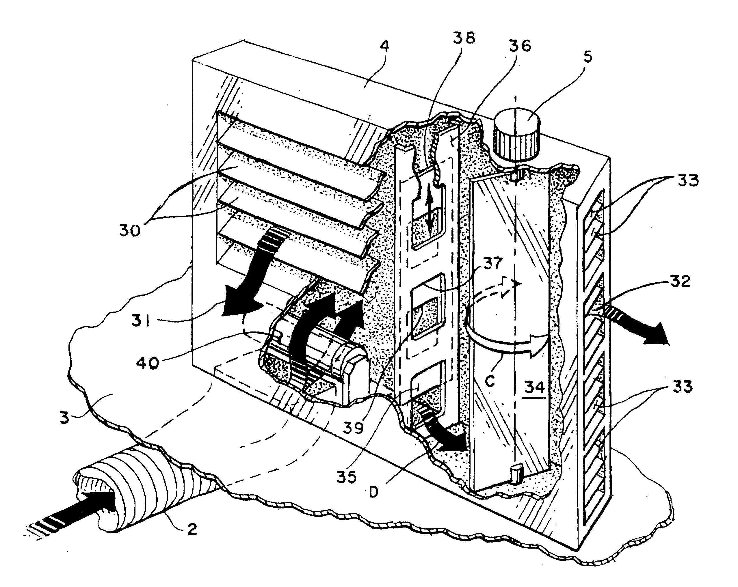
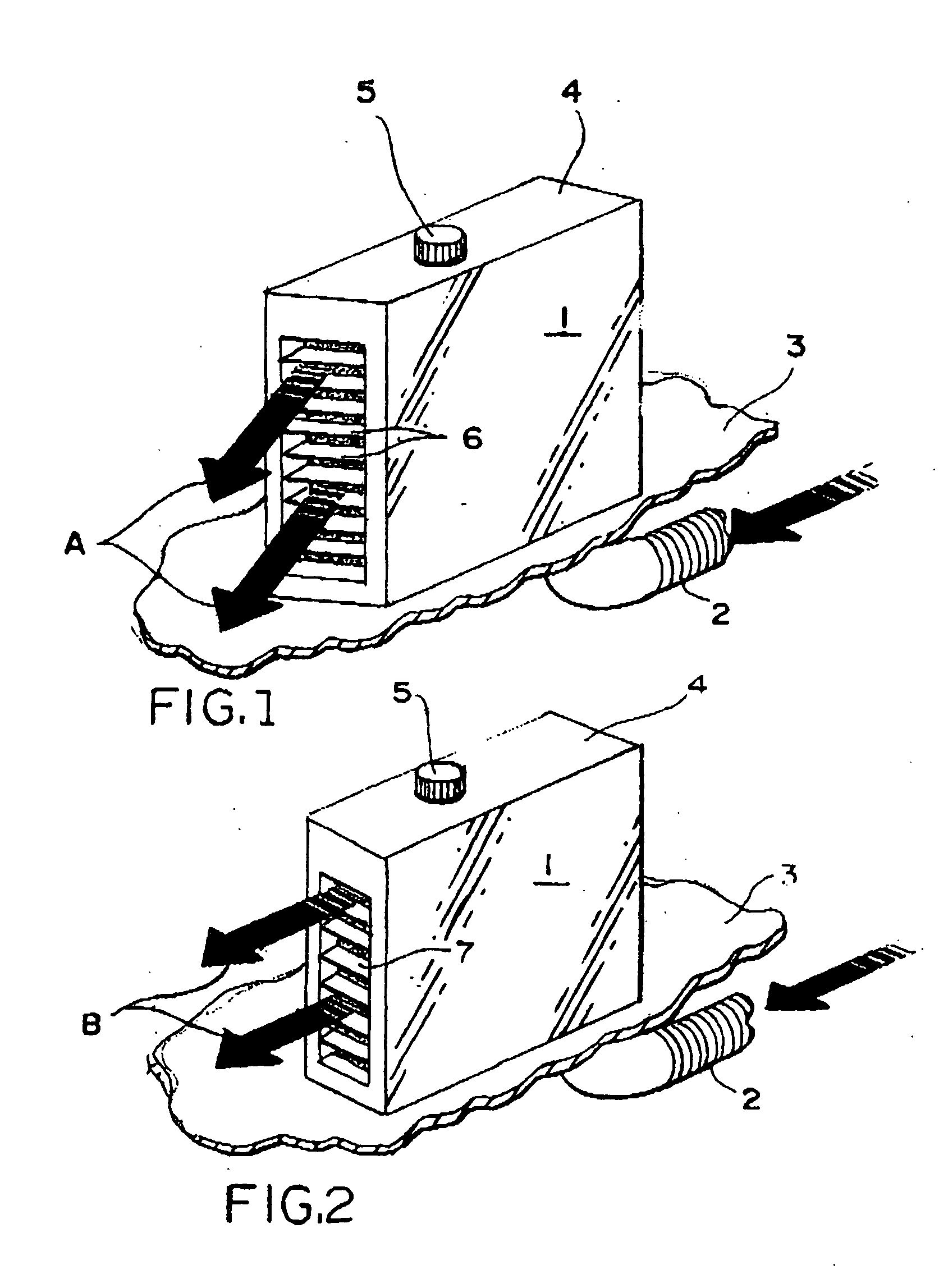
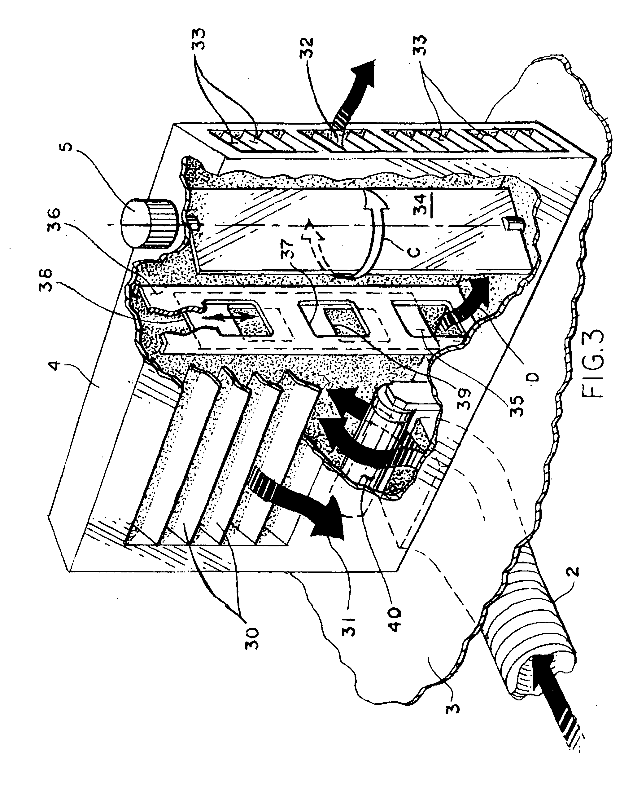
[0036]FIG. 1 is a perspective view of a stand-alone unit which consists of a hollow chamber 1. The stand-alone unit can be placed next to a desk or table representing a work station or any other station involving one or more persons. The unit 1 consists of a hollow chamber 1 which is situated on a floor 3 having a plenum of air conditioned air there below. The conditioned air is fed into the hollow unit 1 by a flexible duct 2 deriving the air from below the floor 3. The unit 1 has a top 4 having a control knob 5 thereon that controls the amount of air passing through the unit 1, as will be explained below. The unit 1 shown in FIG. 1 has a front air outlet that is angled to the right so the air emanating from the front will be directed to the right, possibly to a person sitting or working at that particular work station. The arrows A indicate the direction of the movement of the air through the adjustable louvers 6.

[0037]FIG. 2 illustrates the same layout as is shown in FIG. 1 excep...


PUM


Abstract

A personalized air conditioning/displacement ventilation system is located above a floor having an air plenum below the floor but above the concrete slab. A displacement ventilation stand-alone air chamber is located above the floor and thereby delivers air above the air plenum. The air chamber has a frontal outlet and a lateral air outlet into the ambient atmosphere. Within the stand-alone chamber the air is being displaced in various amounts to various outlets. The stand-alone unit can be placed wherever it is needed or desired in many locations in a wide open work place as a retrofit.

Description

PRIOR APPLICATIONS [0001] This application is a Continuation-In-Part of application Ser. No. 11 / 069,453 having a filing date of Mar. 2, 2005.FIELD OF THE INVENTION [0002] The invention at hand relates to either heating or cooling the air in a large building, especially with a floor area having multiple persons working therein. The invention is directed primarily to the personal comfort of a person working at a workstation including a desk by directing conditioned air to the immediate vicinity of the person or persons present at those workstations and by giving those persons control over the flow and direction of the conditioned air, and to providing displacement ventilation to the surrounding area. BACKGROUND OF THE INVENTION [0003] In the field of heating and cooling, generally known as “air conditioning”, there are known problems causing discomfort to the occupants in the building or a room. Inefficiencies in the system result in excessive operating costs in the operation of the b...

Claims


Application Information

Patent Timeline
IPC IPC(8): F24F7/007F24F7/00
CPCF24F13/06F24F2221/38F24F7/00F24F7/007
Inventor LEVY, HANS F.BETZ, PETER G.
Owner LEVY HANS F
Why Eureka
Try Eureka