
Electronically controlled engine generator set

a generator set and electric motor technology, applied in the direction of electric generator control, hybrid vehicles, electric motor propulsion transmission, etc., can solve the problem that the feedback does not directly control the engine speed, and achieve the effect of avoiding fumes and pollution, and avoiding the need for engine throttling

Inactive Publication Date: 2005-06-02
BOREALIS TECH LTD
View PDF64 Cites 33 Cited by
  • Summary
  • Abstract
  • Description
  • Claims
  • Application Information

AI Technical Summary

Benefits of technology

[0027] A technical advantage of the present invention is that it provides new and improved methods and apparatus for prime mover generator systems and control over them. A further technical advantages is to provide a heat engine generator system in which the heat engine can be continuously operated over a wide load range without induction restriction, avoiding the need for engine throttling.
[0028] Another technical advantage of the present invention is that higher engine efficiency is obtained by avoiding engine operation in a near closed throttle mode. Further, the heat engine does not have to be turned on and off in response to demand, but rather the engine runs steadily. This avoids the fumes and pollution caused when a heat engine starts and prevents the loss of rotational energy that occurs from repeated stopping and starting.
[0029] A further technical advantage of the present invention is that it provides a heat engine generator system in which control is applied to the generator to electronically regulate the output of the system. Thus, control over the output of the system may be faster and more exact. Further, the load on the heat engine may be electrically manipulated to maintain a close to optimal run of the engine.
[0030] A still further technical advantage of the present invention is that it provides a method by which a generator may be operated periodically as a motor. This allows the heat engine operation, during power absorbing strokes, to be improved by a periodic transfer of power from the generator, acting as motor, back to the engine. Thus, the present invention provides a simple method by which an electrical machine may alternate between generator and motor operation without direct control intervention, and without need to synchronize controller operation to heat engine operation.
[0031] Other technical advantages of the present invention are set forth in or will be apparent from drawings and the description of the invention that follows, or may be learned from the practice of the invention.BRIEF DESCRIPTION OF THE SEVERAL VIEWS OF THE DRAWING

Problems solved by technology

In general, feedback does not directly control engine speed, but instead power output.

Method used


Image

  • Electronically controlled engine generator set
  • Electronically controlled engine generator set
  • Electronically controlled engine generator set

Examples


example 1

Changing a Resistive Load on a Generator

[0086] For example, the present invention may be used with a DC generator supplying a resistive load. Similar results will be obtained from a synchronous AC generator supplying a resistive load with no frequency regulation, or to an AC induction generator with passive supply of excitation, (e.g. a capacitive excitation supply). The immediate example will not work with an AC machine operating on a fixed frequency load.

[0087] An engine produces a mechanical power output. This mechanical power is converted by a generator into electrical power. The electrical power is fed to a resistive load where it is dissipated. Due to external control input, decreased power supply is needed (for example, a thermostat has signaled a state of sufficient heat). To reduce the engine power output, the fuel being consumed by the engine is reduced, which is done by slowing the engine down.

[0088] To slow the engine down, the torque load of the generator is increase...

example 3

Power Electronic Pseudo-Resistive Load

[0112] A variable resistive load may be used to control the torque / speed characteristics of a generator, thereby obtaining control of engine / generator speed, engine mechanical power output, and thus, engine / generator electrical power output. Such a load need not be an actual resistor, but may be any load with a generally resistive character. Of specific interest are loads which have positive incremental resistance; loads for which current will increase when voltage increases, even if the ratio of current to voltage is not constant as it would be in a true resistor.

[0113] As noted above, there is generally an increase in output voltage as the generator speeds up. The value of positive incremental resistance is that as the voltage increases, the current drawn by the load will increase, increasing the torque load of the generator. A generator providing power to a load with positive incremental resistance will be stable to perturbations in prime m...

example 4

Power Electronic Pseudo-Resistive Load with Energy Storage

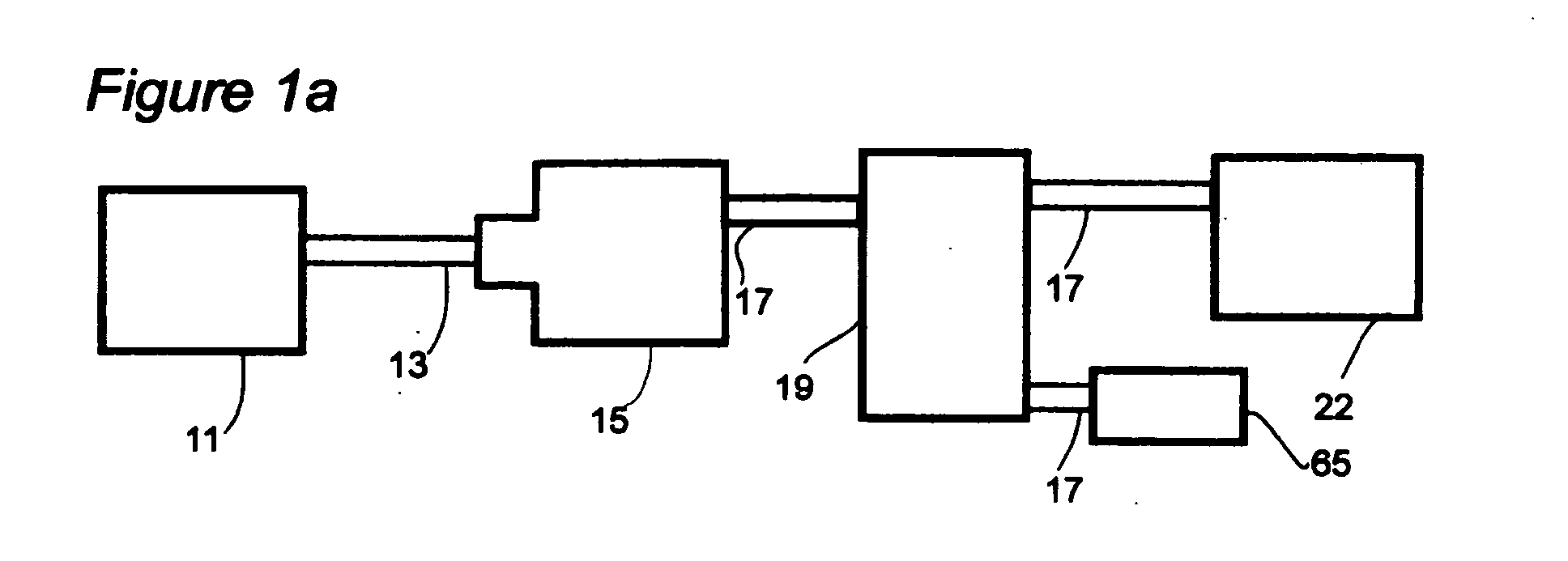
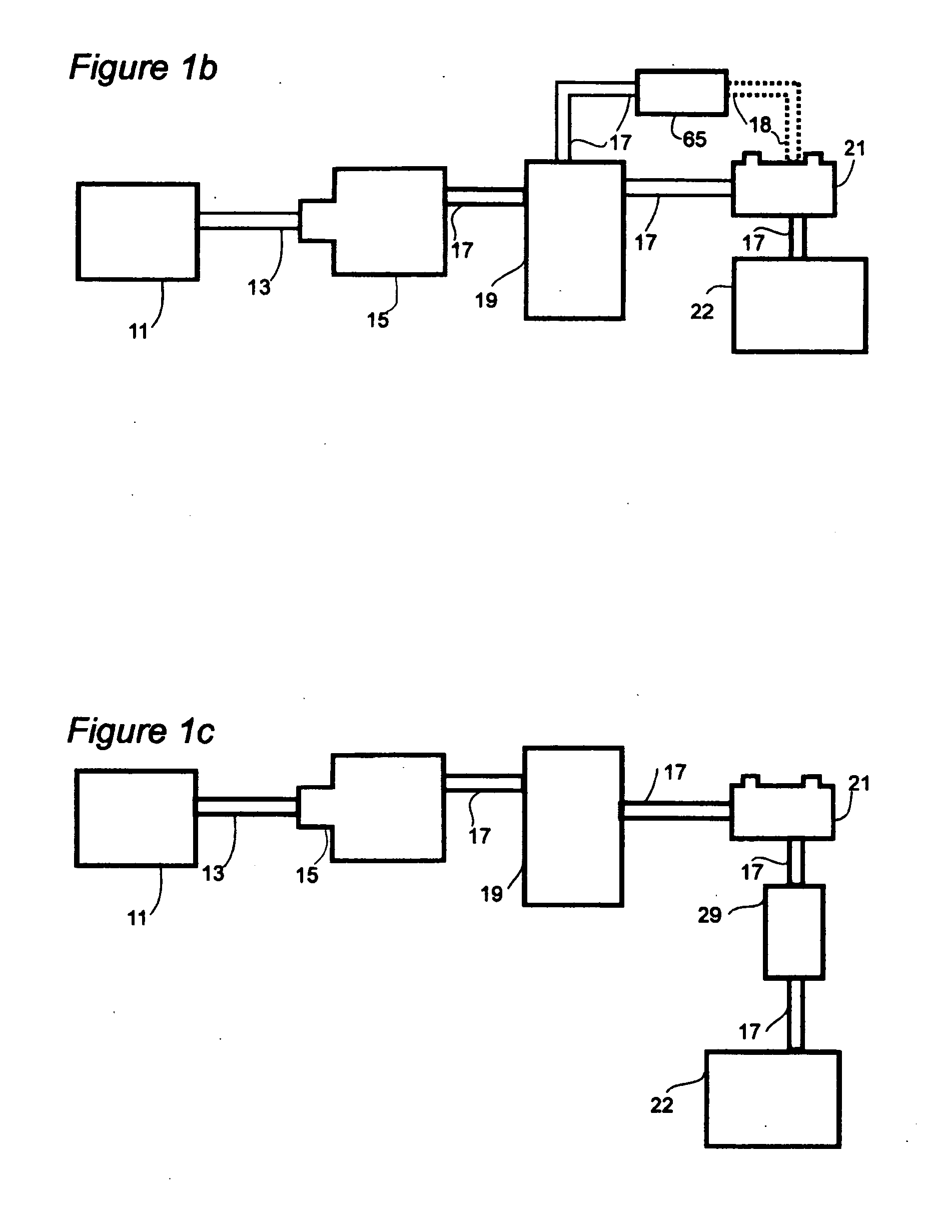
[0123] With the addition of energy storage needed for smooth supply of electrical power to the final load, additional options are available for a power electronic load. A suitably designed power electronic load may be capable of sourcing as well as absorbing power. In some cases, such capability is an inherent part of the load design, in other cases a load must be designed specifically for power sourcing applications. The embodiment may be understood with reference to FIG. 1a. Prime mover 11, which may be a heat engine, is connected via a shaft 13 to generator 15. Control mechanism 19 is connected to the output of generator 15, and is connected to an energy storage unit 21 and to an eventual load 22. The control mechanism 19 in the present embodiment takes the form of a power electronic load, also referred to as a power electronic converter. The power electronic load is capable of controlling the generator power output and a...


PUM


Abstract

An electronically controlled electrical power generator comprises a generator driven by a heat engine, operated by control means, and carrying an electrical load. Operation of the heat engine is at wide open throttle. Control over engine operation and electrical output of the generator is achieved by electronically manipulating the electric load, and / or adjusting excitation levels at the generator's magnetic fields, so as to change engine / generator equilibrium speed. In a beneficial embodiment, the generator is powered by an energy storage unit, to temporarily act as a motor and rotate the engine when starting, and during power absorbing strokes.

Description

CROSS-REFERENCE TO RELATED APPLICATIONS [0001] This application is a divisional application of Application Ser. No. 09 / 675,082 filed Sep. 28, 2000, which claims the benefit of U.S. Provisional Application No. 60 / 156,402, filed Sep. 28, 1999. The above-mentioned patent applications are assigned to the assignee of the present application and are herein incorporated in their entirety by reference.BACKGROUND OF THE INVENTION [0002] The present invention is related to the field of electric power production using combustion engines. It is further related to methods of control of electric power systems responding to load changes. [0003] In an engine / generator system, the fuel supply to the prime mover is directly controlled by an actuator means, generally with a throttle or injection pump. Fuel supply adjustment is a method of adjusting the torque / speed characteristics of the prime mover. As the throttle is closed or the fuel injection setting reduced, the torque produced at a given rotati...

Claims


Application Information

Patent Timeline
IPC IPC(8): B60L50/11B60L50/15H02P9/04
CPCB60L11/04B60L11/12H02P9/04H02P2101/15Y02T10/642H02P2101/10Y02T10/7077B60L50/11B60L50/15Y02T10/64Y02T10/7072
Inventor EDELSON, JONATHAN SIDNEY
Owner BOREALIS TECH LTD
Learn More