Autonomous electro-optical framing camera system with constant ground resolution, unmanned airborne vehicle therefor, and methods of use

a camera system and electrooptical technology, applied in the field of autonomous electrooptical framing camera system with constant ground resolution, unmanned airborne vehicle therefor, and methods of use, can solve the problems of rare insufficient supply, unique restrictions on payloads that they carry, and inability to provide just enough,

Inactive Publication Date: 2000-10-10
THE BF GOODRICH CO
View PDF19 Cites 291 Cited by
  • Summary
  • Abstract
  • Description
  • Claims
  • Application Information

AI Technical Summary

Problems solved by technology

In military reconnaissance, it is frequently not sufficient to just provide an image of the target itself, but imagery of the surrounding terrain is required as well.
UAVs have been developed by the United States and other countries for military and civilian purposes and are gaining rapidly in their acceptance as a viable mission platform because of their small size, inexpensive procurement and operating cost, limited or no human risk and in some cases, long endurance.
However, these advantages also place unique restrictions on the payloads that they carry, including the reconnaissance cameras.
However, in the case of high altitude, long endurance UAVs, the man-in-the-loop up-link control is no longer always available.
As such, the patent is not truly an autonomous system and would not be suitable for an autonomous system or an UAV type of environment.

Method used


Image

  • Autonomous electro-optical framing camera system with constant ground resolution, unmanned airborne vehicle therefor, and methods of use
  • Autonomous electro-optical framing camera system with constant ground resolution, unmanned airborne vehicle therefor, and methods of use
  • Autonomous electro-optical framing camera system with constant ground resolution, unmanned airborne vehicle therefor, and methods of use

Examples


Embodiment Construction

I. Overview and General Discussion

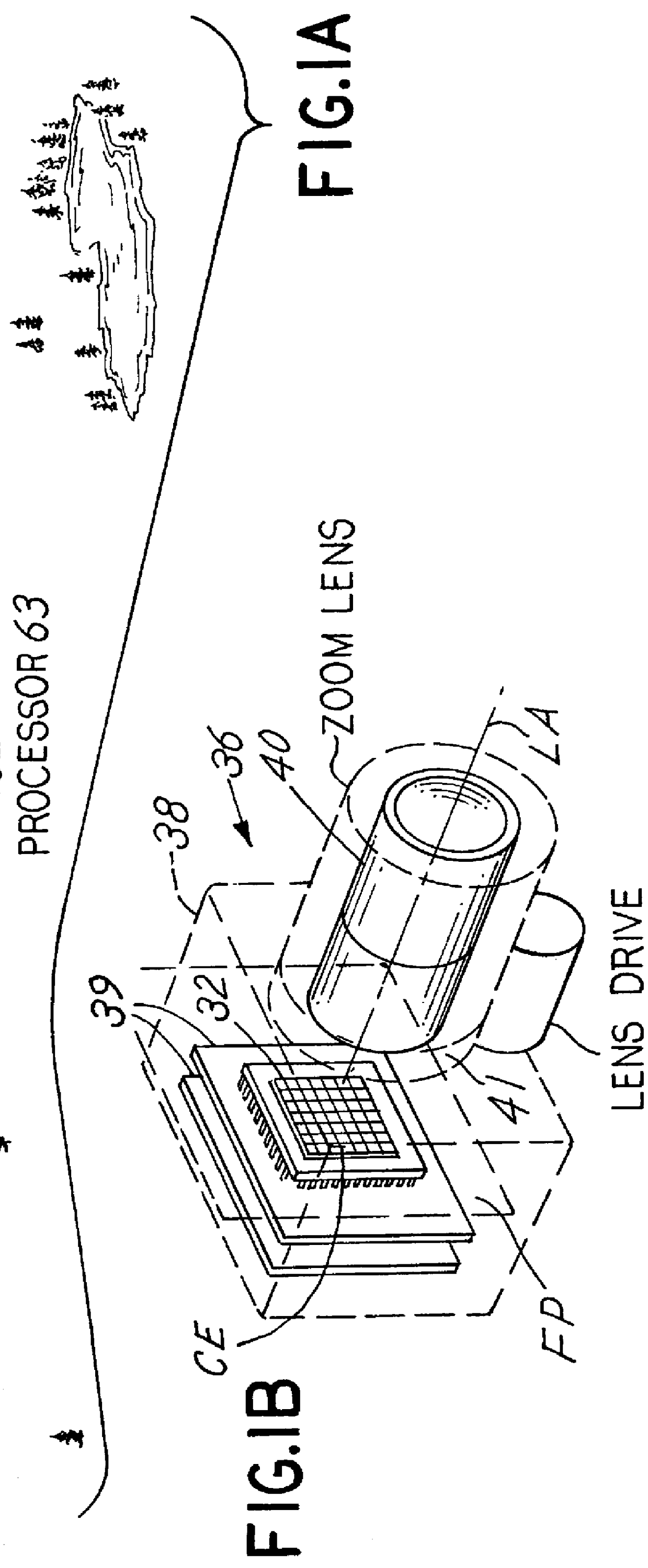
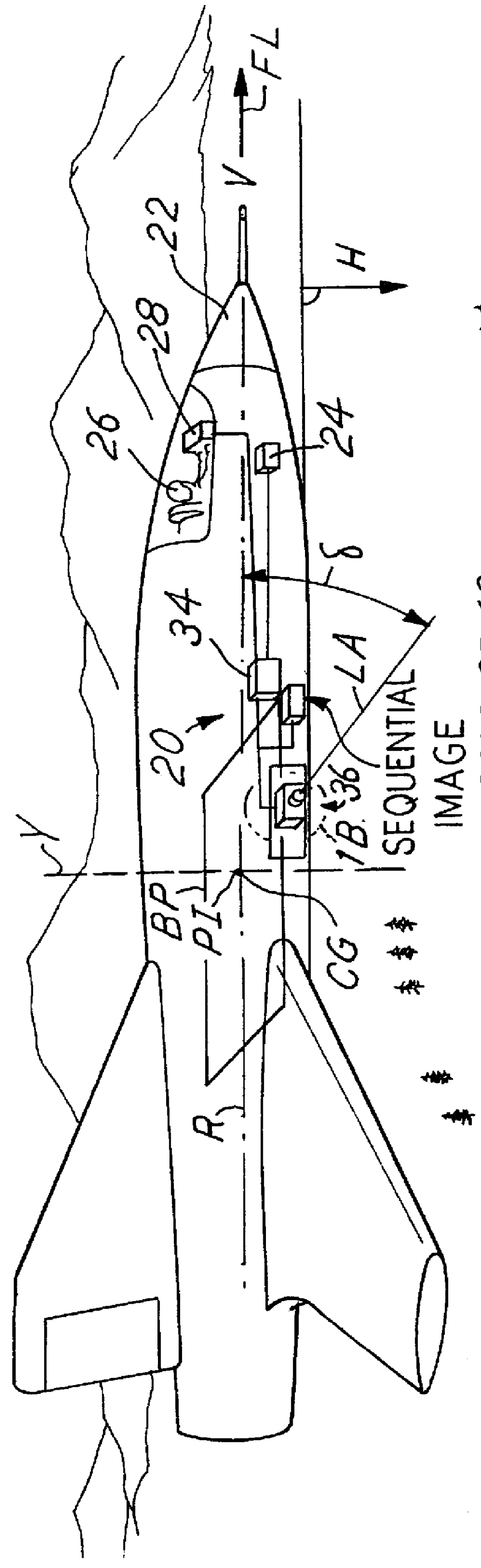
FIG. 1A is an illustration of a reconnaissance aircraft 22 performing a reconnaissance mission. An aerial reconnaissance system 20 including a camera system 36 is installed inside the aircraft 22, and is shown taking a series of frames of imagery in a side oblique orientation. In accordance with one possible embodiment of the invention, the camera system 36 performs calculations of the range to the target from previous frames of imagery. The camera control computer 34 sets the focal length of a zoom lens in the system 36 to yield imagery having a constant ground resolution, field of view or NIIRS objectives in accordance with the techniques described herein. Additionally, the camera system includes an imaging array that performs forward motion compensation. The manner in which forward motion compensation is achieved is not particularly important, and can be by any of several known methods.

The aircraft 22 defines orthogonal roll, pitch and yaw axes R...


PUM


Abstract

An aerial reconnaissance system generates imagery of a scene that meets resolution or field of view objectives automatically and autonomously. In one embodiment, a passive method of automatically calculating range to the target from a sequence of airborne reconnaissance camera images is used. Range information is use for controlling the adjustment of a zoom lens to yield frame-to-frame target imagery that has a desired, e.g., constant, ground resolution or field of view at the center of the image despite rapid and significant aircraft altitude and attitude changes. Image to image digital correlation is used to determine the displacement of the target at the focal plane. Camera frame rate and aircraft INS / GPS information is used to accurately determine the frame to frame distance (baseline). The calculated range to target is then used to drive a zoom lens servo mechanism to the proper focal length to yield the desired resolution or field of view for the next image. The method may be performed based on parameters other than range, such as aircraft height and stand off distance.

Description

This invention relates generally to the art of aerial reconnaissance photography, and more particularly to a reconnaissance camera system having an electro-optical imaging sensor or array with zoom lens capability that automatically and autonomously achieves desired ground resolution or field of view objectives for the reconnaissance mission. The invention also relates to a method of using such a sensor to generate images with desired ground resolution, field of view, or image interpretability objectives regardless of the changes in velocity or height of an aerial reconnaissance vehicle incorporating the sensor. The invention also relates to an unmanned aerial vehicle that incorporates the reconnaissance camera system that operates autonomously to meet reconnaissance mission objectives. The camera system can be pre-programmed to capture high resolution images with desired, e.g., constant, ground resolution, field of view or image interpretability value without any human or operator ...

Claims


Application Information

Patent Timeline
Patent Type & Authority Patents(United States)
IPC IPC(8): G01C11/02G01C3/08G01C11/00H04N5/232
CPCG01C3/08G01C11/02H04N5/23287H04N5/23254H04N5/23264H04N5/23248H04N23/68H04N23/6811H04N23/682H04N23/687
Inventor LAREAU, ANDRE G.BERAN, STEPHEN R.JAMES, BRIANQUINN, JAMES P.LUND, JOHN
Owner THE BF GOODRICH CO
Why Eureka
Try Eureka