Cover mounting assembly

a technology for mounting brackets and covers, applied in the direction of couplings/cases/cabinets/drawers, coupling device connections, electrical apparatus casings/cabinets/drawers, etc., can solve the problem of inconvenience for users

Inactive Publication Date: 2006-10-19
HONG FU JIN PRECISION IND (SHENZHEN) CO LTD +1
View PDF9 Cites 17 Cited by
  • Summary
  • Abstract
  • Description
  • Claims
  • Application Information

AI Technical Summary

Problems solved by technology

However, to take out the covers, users have to find a screwdriver to unscrew the screws, and it is very inconvenient for the users.

Method used


Image

  • Cover mounting assembly
  • Cover mounting assembly
  • Cover mounting assembly

Examples


Embodiment Construction

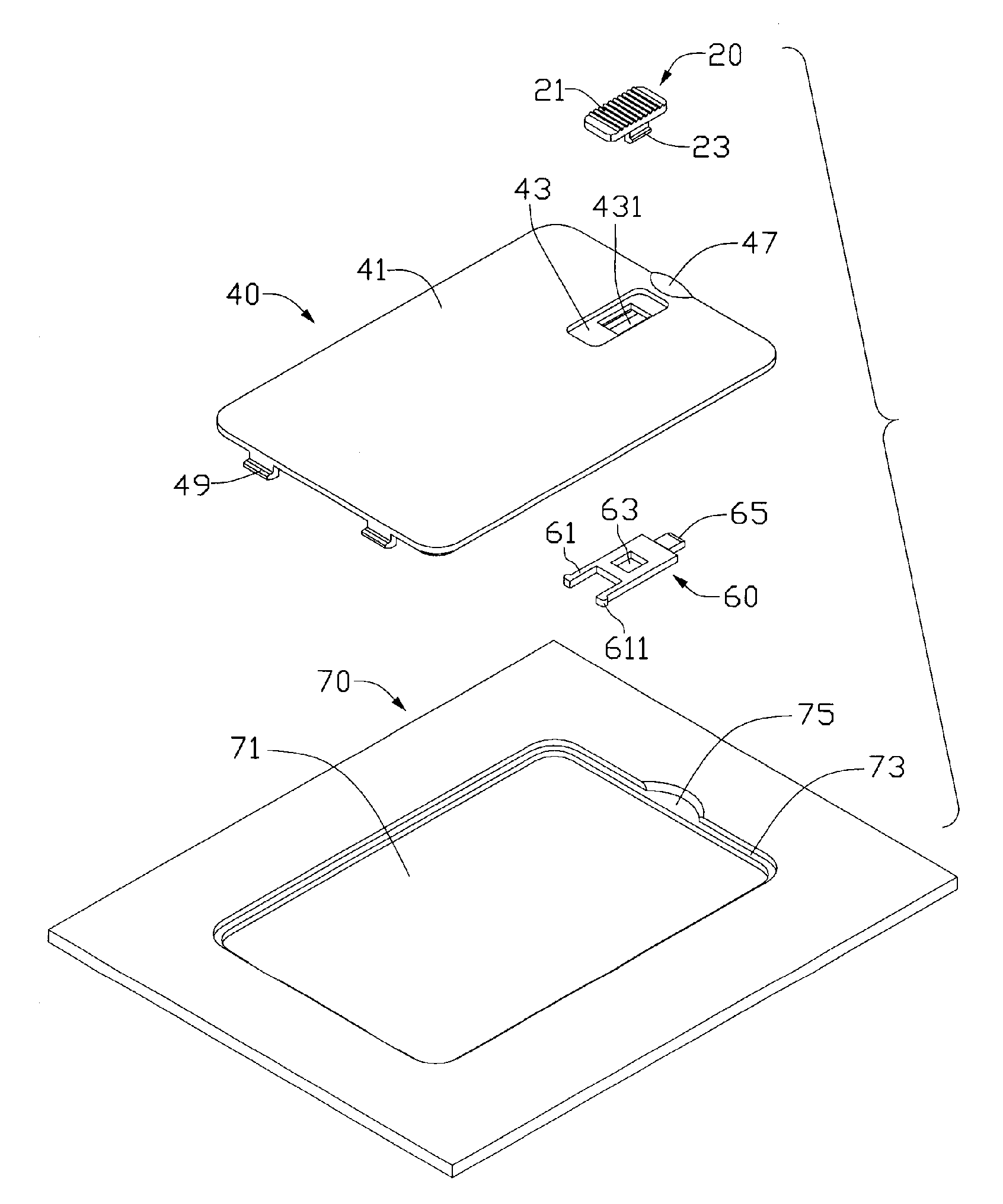
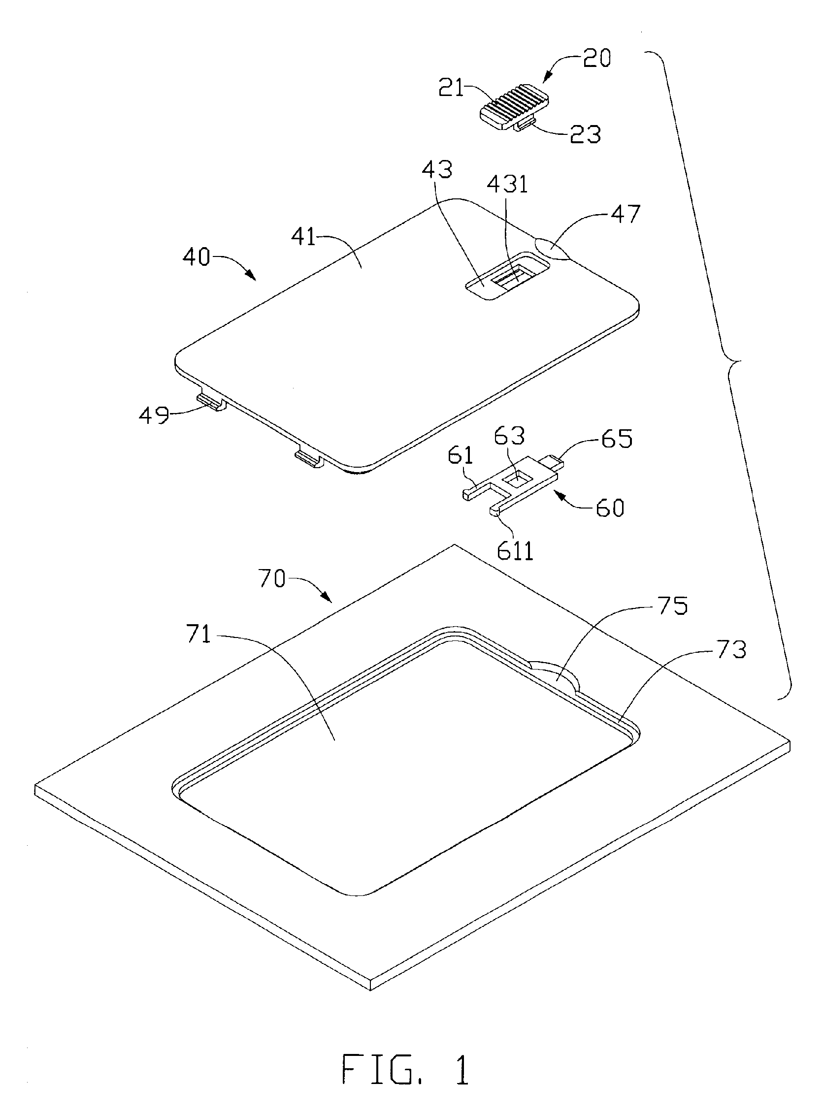
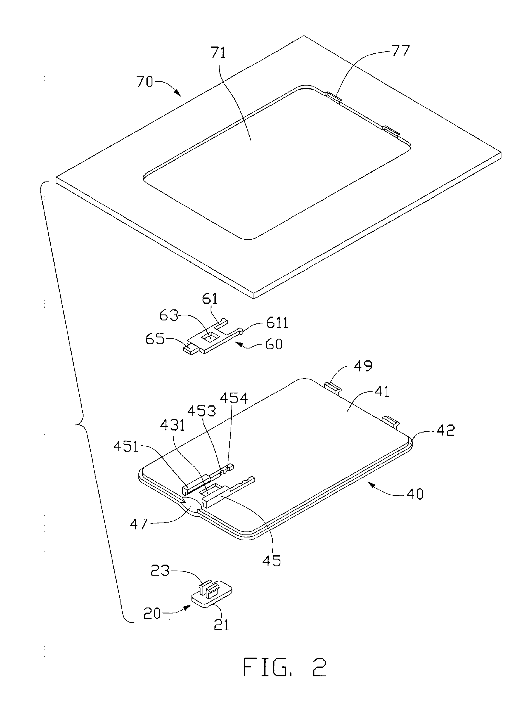
[0010] Referring to FIGS. 1 and 2, a cover mounting assembly in accordance with a preferred embodiment of the present invention includes a button 20, a cover 40, a locking member 60 to be slidably assembled on the cover 40 by the button 20, and a base plate 70 of a portable electronic device with an opening 71 for receiving the cover 40. The cover mounting assembly protects internal components of the portable electronic device, and also prevents the dust coming into the portable electronic device.

[0011] The button 20 includes a pushing portion 21 and a pair of flexible catches 23 formed at opposite sides of the pushing portion 21.

[0012] The cover 40 includes a rectangular main body 41 with stepped side edges 42. A receiving portion 43 is formed at a front portion of the main body 41, and a through hole 431 is defined in the receiving portion 43 corresponding to the catches 23 of the button 20. A pair of fixing portions 45 is formed from the internal surface of the cover 40, and ea...


PUM


Abstract

A cover mounting assembly includes a button (20), a cover (40), a locking member (60) and a base plate (70). The cover includes a pair of hooks (49). The locking member includes a lockpin (65). The locking member is attached with the button on the opposite surfaces of the cover to slide forward or rearward together. The base plate includes an opening (71) and a pair of slots (77). The cover is received in the opening of the base plate and the hooks are received in the slots of the base plate respectively. The lockpin of the locking member abuts against the internal surface of the base plate to fasten the cover to the base plate.

Description

FIELD OF THE INVENTION [0001] The present invention relates to a cover mounting assembly, and more particularly to a cover mounting assembly which is applied to a portable electronic device to prevent dust. DESCRIPTION OF RELATED ART [0002] Generally, a base plate of portable electronic device forms several receiving spaces for receiving components, such as batteries, memories, hard disks, and heat sinks. When the components are received in the corresponding receiving spaces, in order to protect the components and prevent the dust in the air coming into the receiving spaces to contaminate and even damage the portable electronic device, each opening of the receiving spaces is covered by a cover. [0003] Some covers of the openings are secured on the base plate by screws. However, to take out the covers, users have to find a screwdriver to unscrew the screws, and it is very inconvenient for the users. [0004] What is desired, therefore, is a cover mounting assembly which has no screws. ...

Claims


Application Information

Patent Timeline
Patent Type & Authority Applications(United States)
IPC IPC(8): H01R13/52
CPCH05K5/0221G11B33/027
Inventor SHI, ZHENGCHEN, ZHI-GANGPENG, XIONG-DONGLIN, KE-CHEUNGTSAI, CHIEN-LI
Owner HONG FU JIN PRECISION IND (SHENZHEN) CO LTD
Why Eureka
Try Eureka