Jet engine with compact arrangement of fan

Inactive Publication Date: 2006-10-26
MTU AERO ENGINES GMBH
View PDF3 Cites 52 Cited by
  • Summary
  • Abstract
  • Description
  • Claims
  • Application Information

AI Technical Summary

Benefits of technology

[0008] Further preferably according to particular example embodiments of the invention, the conventional arrangement of a bearing star or spider between the fan and the low pressure compressor is avoided, i.e. there is no such bearing element between the fan and the low pressure compressor. Thereby, the fan is arranged directly neighboring and upstream from the low pressure compressor, in such a manner so th

Problems solved by technology

These features leading to a large structural length of the jet engine further bring about

Method used


Image

  • Jet engine with compact arrangement of fan
  • Jet engine with compact arrangement of fan
  • Jet engine with compact arrangement of fan

Examples


Example

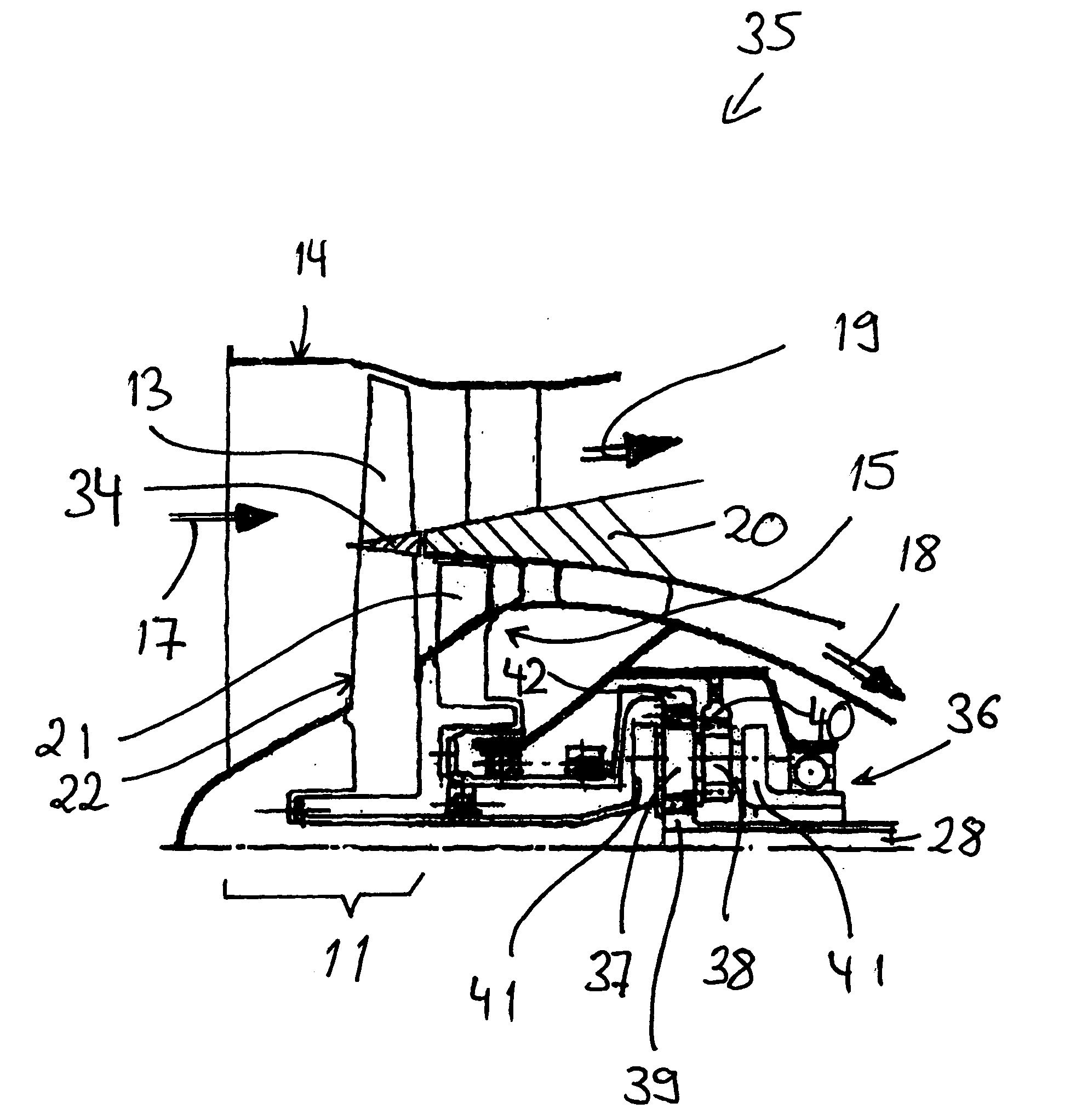
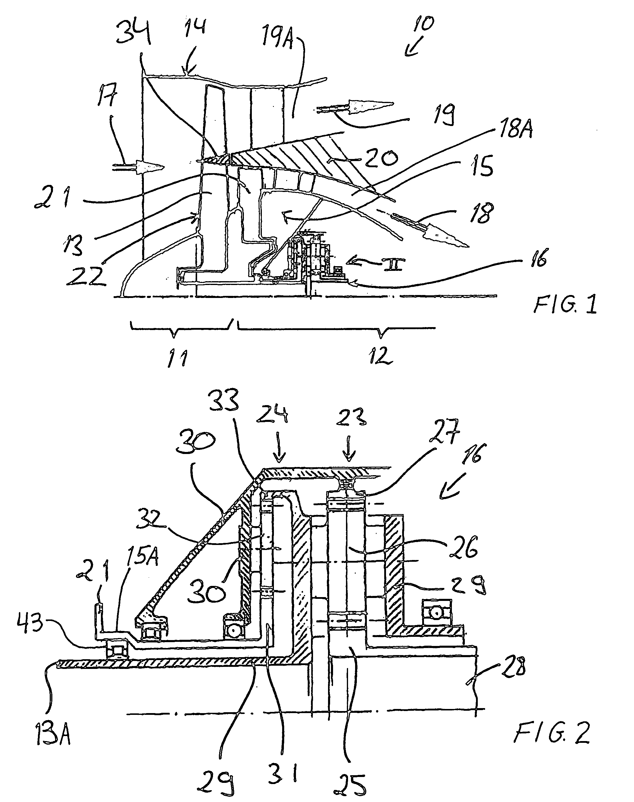
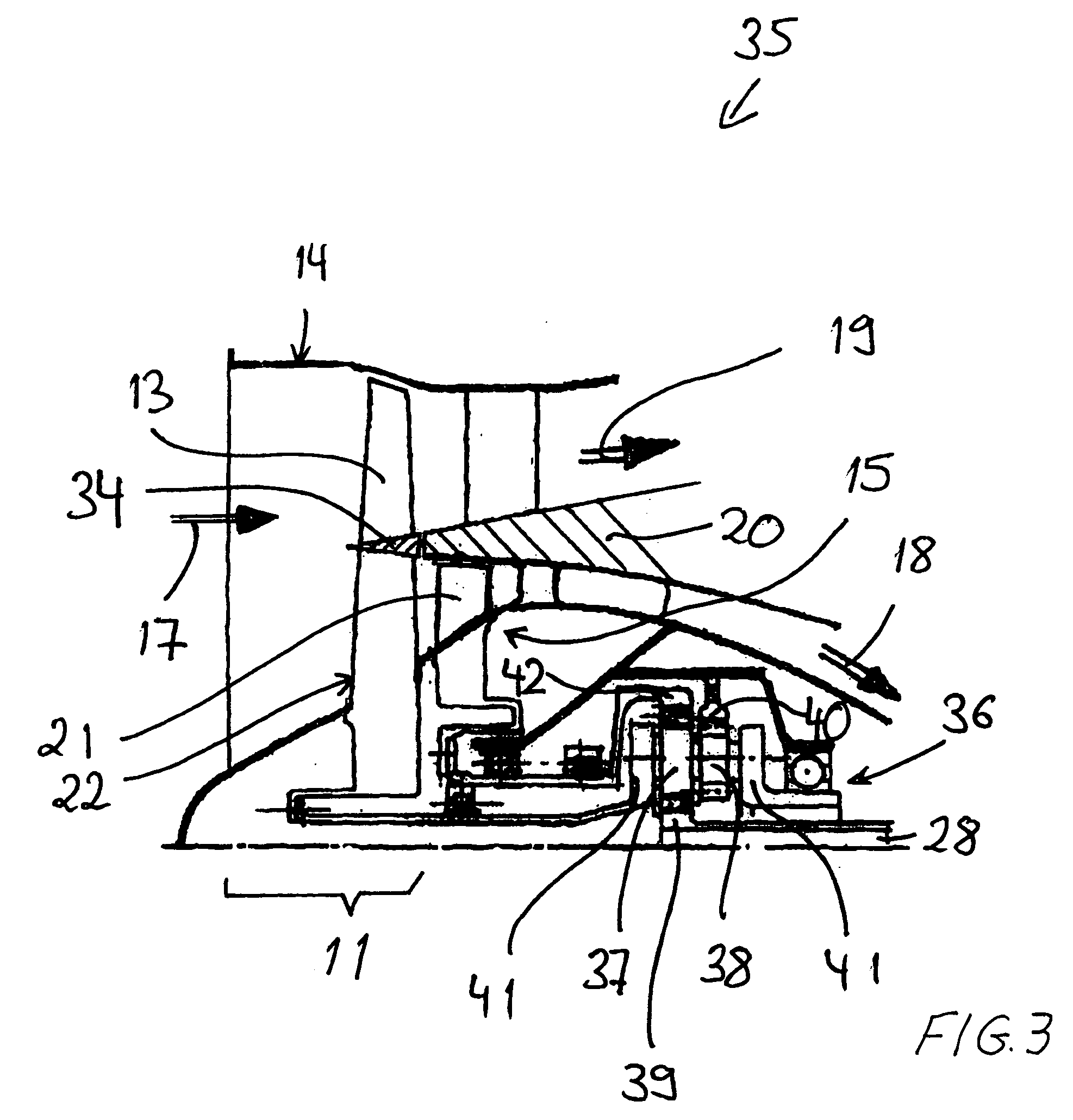
[0014] The general arrangement of major components of a conventional jet engine as shown in FIG. 4 has been discussed above in the Background Information section. Jet engines according to example embodiments of the present invention include some components similar to the conventional engine, such as the two compressors, the combustion chamber, and the two turbines. The significant differentiated features of the inventive embodiments will now be discussed in further detail in connection with the partial views of FIGS. 1 to 3 focusing on the arrangement of the fan, the low pressure compressor, and the transmission.

[0015]FIG. 1 shows a portion of a jet engine 10 embodied as a bypass or two circuit jet engine, which generally comprises a fan module 11 as well as a core engine 12. The fan module 11 comprises a fan 13 and a fan housing or casing 14. In the present example embodiment, the core engine 12 comprises a single-stage low pressure compressor 15 as well as further components arra...


PUM


Abstract

A jet engine includes a fan arranged upstream of a core engine having a low pressure compressor, a high pressure compressor, a combustion chamber, a high pressure turbine, and a low pressure turbine. The high pressure turbine is drive-connected to the high pressure compressor. The low pressure turbine is drive-connected through a transmission to the low pressure compressor and to the fan, which are respectively driven in opposite rotation directions. A compressor disk of the low pressure compressor is positioned downstream directly after the fan so that a hub end section of the fan and the compressor disk together form a counter-rotating compressor stage.

Description

PRIORITY CLAIM [0001] This application is based on and claims the priority under 35 U.S.C. §119 of German Patent Application 10 2005 018 139.2, filed on Apr. 20, 2005, the entire disclosure of which is incorporated herein by reference. FIELD OF THE INVENTION [0002] The invention relates to a jet engine comprising a bypass fan as well as a core engine that includes a low pressure compressor, a high pressure compressor, a combustion chamber, a high pressure turbine, and a low pressure turbine. BACKGROUND INFORMATION [0003] The essential basic components of a typical jet engine are a core engine embodied as a gas turbine engine, and a fan module arranged upstream of the core engine. A total intake airflow that flows through the fan module is divided into a core engine airflow that is provided into the core engine, and a bypass airflow that bypasses or flows outwardly past the core engine. Such bypass jet engines are also designated as two circuit jet engines. [0004] As generally schema...

Claims


Application Information

Patent Timeline
IPC IPC(8): F02K3/02F02K3/10
CPCF02C3/067F02C3/073F02K3/06F05D2260/40311Y02T50/671F05D2220/326F05D2220/327F02K3/072Y02T50/60
Inventor WEILER, WOLFGANG
Owner MTU AERO ENGINES GMBH
Why Eureka
Try Eureka