Micro component liquid hydrocarbon steam reformer system and cycle for producing hydrogen gas

Inactive Publication Date: 2008-09-04
SEABA JAMES +1
View PDF10 Cites 0 Cited by
  • Summary
  • Abstract
  • Description
  • Claims
  • Application Information

AI Technical Summary

Benefits of technology

[0006]Prior art convention in fuel cell technology, generally in automotive applications, employs an auto-thermal reforming system that, through a sequence of known chemical reactions, converts hydrocarbons, water and air into hydrogen-enriched gas that feeds a fuel cell. Steam reformer systems are known; but the art is skeptical of the adaptability of steam reformer systems for motor vehicle use. See“Fuel Cell Technology,” Automotive Engineer, September 2000, p

Problems solved by technology

The use of fuel cells (despite their desirable characteristics) in motor vehicles, transportation, mobile and “small scale” applications (varying from powering a laptop computer to providing power for an entire home), where a discrete source of hydrogen is required

Method used


Image

  • Micro component liquid hydrocarbon steam reformer system and cycle for producing hydrogen gas
  • Micro component liquid hydrocarbon steam reformer system and cycle for producing hydrogen gas
  • Micro component liquid hydrocarbon steam reformer system and cycle for producing hydrogen gas

Examples


example i

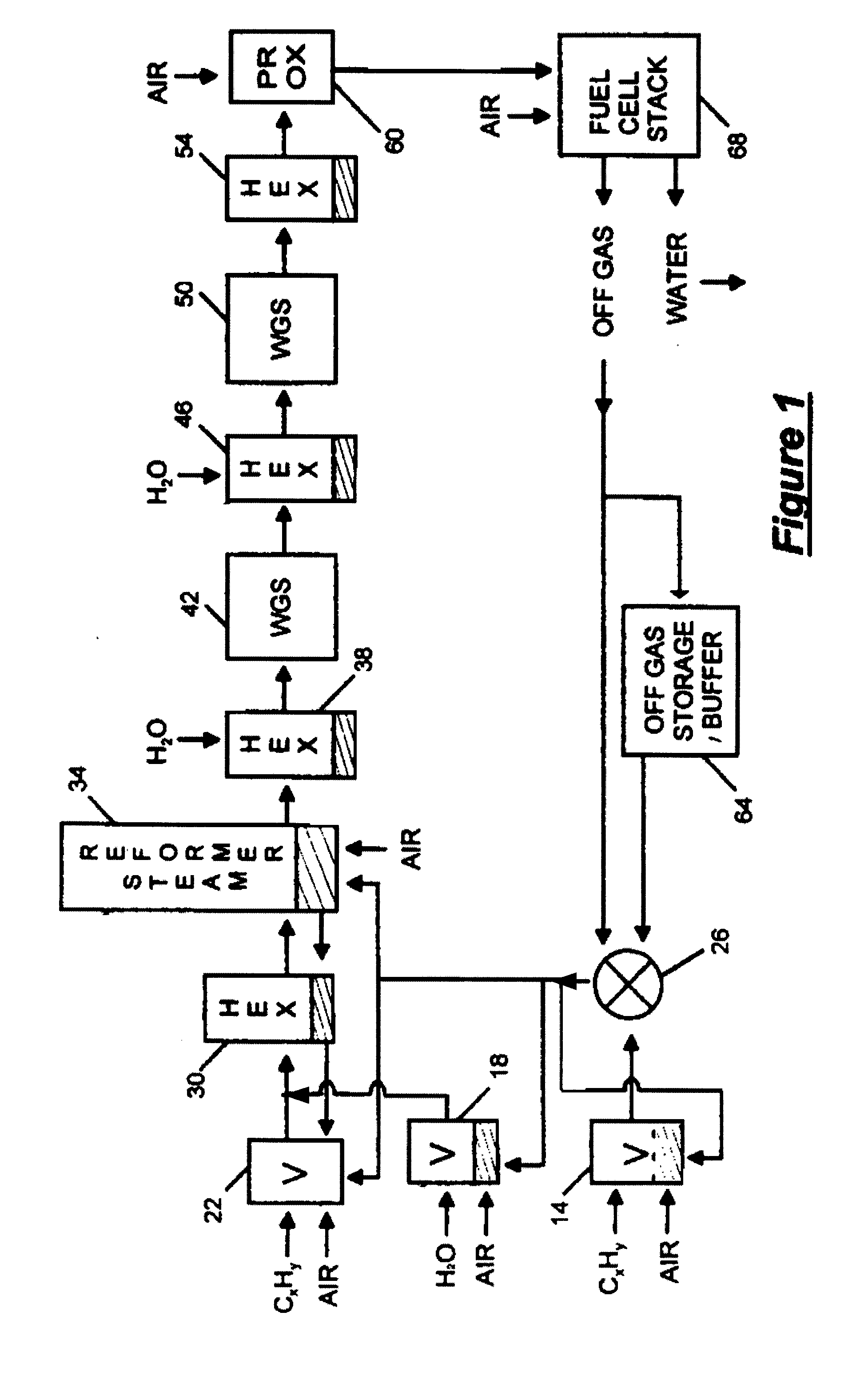
[0023]With reference to FIG. 1, a fuel processor for processing hydrocarbon fuel to produce hydrogen includes first and second fuel vaporizers 14 and 22, water vaporizer 18, mixer 26 for mixing vaporized fuel and fuel cell off gas, first heat exchanger 30, steam reformer 34, second heat exchanger 38, first water gas shift reactor 42, third heat exchanger 46, second water gas shift reactor 50, fourth heat exchanger 54, preferential oxidation reactor 60, storage tank 64 for storing fuel cell off gas, and fuel cell stack 68.

[0024]In the fuel processor, a hydrocarbon fuel, preferably a liquid fuel such as gasoline is vaporized by the first fuel vaporizer 14. (In an embodiment, energy for vaporizer 14 may be provided by the combustion of fuel cell off gas maintained in a buffer or other storage.) The vaporized fuel is mixed with stored fuel cell off gas, or hydrogen, from storage tank 64 in mixer 26 until the fuel processor is heated and running, at which point the vaporized liquid hydro...

example ii

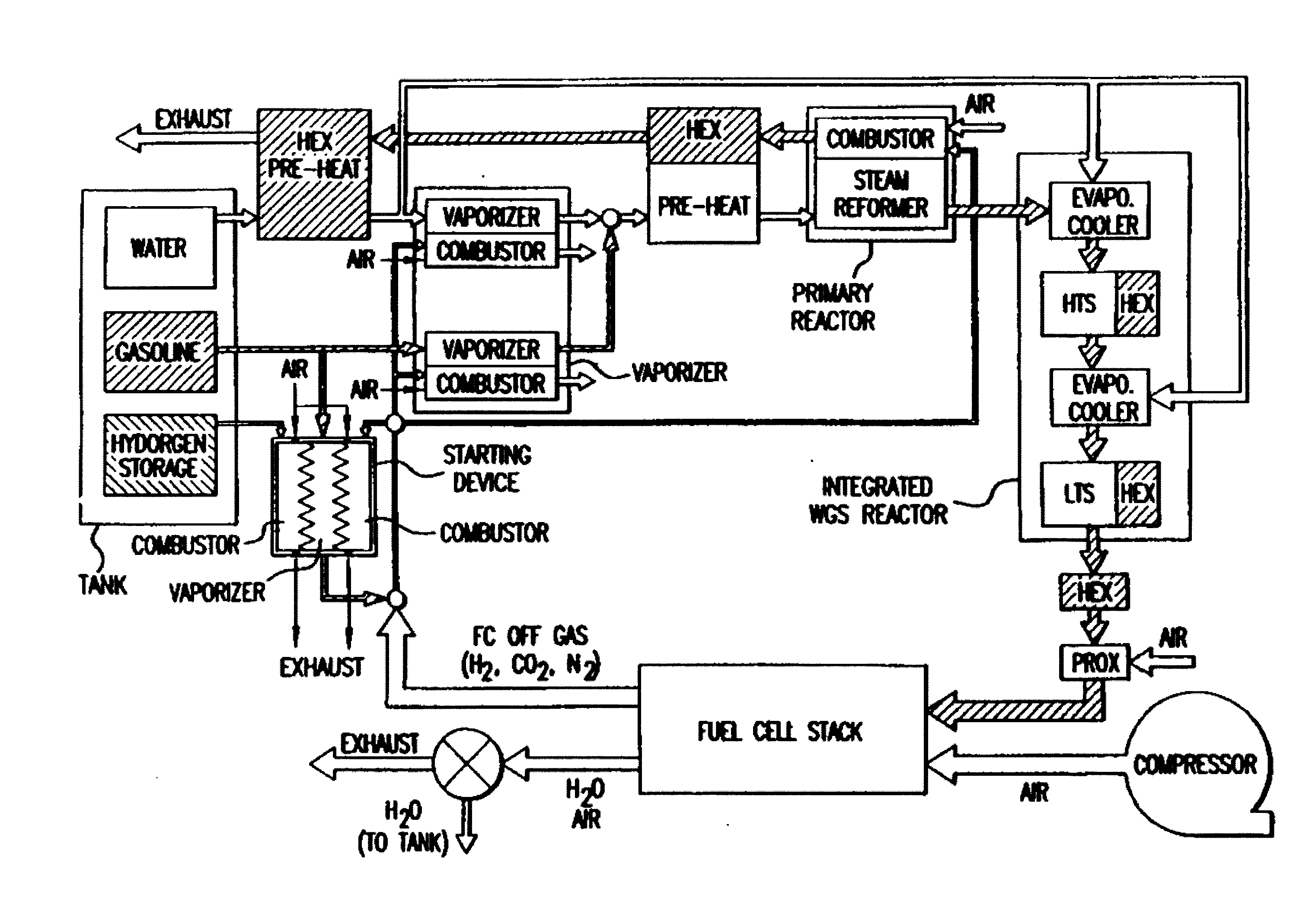
[0040]A second example is shown in FIG. 4. In operation, the process is self-sustaining from fuel sources of hydrocarbons and water. A balanced isothermal reactor is provided that converts gasoline and water into hydrogen enriched gas that powers the fuel cell bank. The gasoline vapor supplies all combustors used for heating in the system; gasoline is both a fuel (as a source of heat for the combustors) and the raw material used in the production of hydrogen enriched gas. In the combustors, heat is generated from gasoline by means of a catalytic combustion reaction induced by a catalyst. Heat is transferred to the fluid on the opposite side of the separator as explained above. Stored hydrogen is used only when the system is started to initiate combustion in the first vaporizer.

[0041]FIG. 4 shows the system in conjunction with a starting device and a fuel tank and also illustrates the relationships of the micro component modules and their sections as involved in fluid flow in the sys...


PUM

PropertyMeasurementUnit
Fractionaaaaaaaaaa
Angleaaaaaaaaaa
Angleaaaaaaaaaa

Abstract

A micro component steam reformer system for producing hydrogen-enriched gas to power a fuel cell adapted for scalable power requirements wherein fluid flow is configured in a circuit whereby, in serially interconnected fluid flow modules, a vaporized hydrocarbon is mixed with fuel cell off gas having a hydrogen component and combusted to heat vaporizers and a steam reformer, vaporized hydrocarbons and water vapor are introduced as a feed stock into the steam reformer to produce a syn-gas, which is cooled and purified, and the resulting principally hydrogen gas is introduced into a hydrogen fuel cell having an interconnection within the circuit in which off gas from the fuel cell is processed to provide hydrogen and water for use in the system cycle.

Description

CROSS-REFERENCE TO RELATED APPLICATIONS[0001]This application is a continuation of our co-pending application Ser. No. 10 / 689,246 filed on Oct. 20, 2003, which in turn was a continuation of application Ser. No. 09 / 803,592 filed on Mar. 9, 2001, now abandoned, both titled Micro Component Liquid Hydrocarbon Reformer System and Cycle for Producing Hydrogen Gas, and a continuation in part of our co-pending application Ser. No. 09 / 847,727 filed on May 2, 2001 which issued as U.S. Letters Pat. No. 6,716,400 on Apr. 6, 2004 titled Ignition System For a Fuel Cell Hydrogen Generator.”BACKGROUND OF THE INVENTION[0002]The present invention relates to a micro component hydrocarbon steam reformer system for producing hydrogen gas and a reaction cycle useful in the system. Particularly, the system relates to micro component apparatus and cycles useful in powering fuel cells adapted for motor vehicle use and other discrete systems having incremental and / or scalable energy requirements.[0003]Hydrog...

Claims


Application Information

Patent Timeline
IPC IPC(8): B01J19/00B01J7/00B01B1/00C01B3/00C01B3/32C01B3/38H01M8/04H01M8/06
CPCB01B1/005Y02E60/324B01J2219/00873C01B3/0005C01B3/323C01B3/384C01B2203/0233C01B2203/0244C01B2203/044C01B2203/047C01B2203/066C01B2203/0805C01B2203/0811C01B2203/0816C01B2203/0822C01B2203/0844C01B2203/0866C01B2203/0877C01B2203/1223C01B2203/1229C01B2203/1247C01B2203/1288C01B2203/142C01B2203/148C01B2203/1604C01B2203/80C01B2203/82H01M8/04022H01M8/04223H01M8/0612Y02E60/50B01J2219/00781Y02E60/32Y02P20/10H01M8/04225H01M8/0258H01M8/0267
Inventor SEABA, JAMESBROOKS, CHRISTOPHER J.
Owner SEABA JAMES
Why Eureka
Try Eureka