Bonding apparatus, bonding method and bonding control program

Active Publication Date: 2018-11-15
KAIJOO KK
View PDF23 Cites 1 Cited by
  • Summary
  • Abstract
  • Description
  • Claims
  • Application Information

AI Technical Summary

Benefits of technology

[0024]As described above, the present invention is capable of performing bonding processing on the plurality of bonding sections of different separation distances with respect to the reference (origin) position of the object to be bonded without changing the moving distance of the bonding means through correcting the separation distances of the bonding sections of the object to be bonded with respect to the bonding means by rotating the bonding stage about the rotation axis.
[0025]In the present invention, the bonding stage is rotated about the rotation axis. Thus, when performing bonding processing by the bonding means, the orientation of the bonding stage with respect to the bonding means is expected to become an issue. Therefore, the present invention utilizes the rotary mechanism for rotating the bonding stage to apply a torque to the bonding stage for enabling stabilization of the orientation for bonding.
[0026]Further, through employing a simple mechanism that rotates the bonding stage without changing the moving distance of the bonding means, the present invention is not only capable of performing the bonding processing on a plurality of bonding sections of different heights without complicating the mechanism of the bonding apparatus but also capable of effectively performing bonding processing on the plurality of bonding sections of different heights disposed on three or more faces even when the plurality of bonding sections of different heights are disposed on the three or more faces of a chip.
[0027]Further, for bonding the object to be bonded having bonding faces in a flat face in a reference orientation and an opposing face perpendicular to the flat face, conventionally performed are bonding on one of the opposing faces, repositioning of the object to be bonded to a state rotated by 180 degrees by an operator, and then bonding on the other opposing face by rotating an inversion mechanism. The present invention, however, requires no such repositioning by the operator for per

Problems solved by technology

Therefore, bonding cannot be achieved wit

Method used


Image

  • Bonding apparatus, bonding method and bonding control program
  • Bonding apparatus, bonding method and bonding control program
  • Bonding apparatus, bonding method and bonding control program

Examples


Example

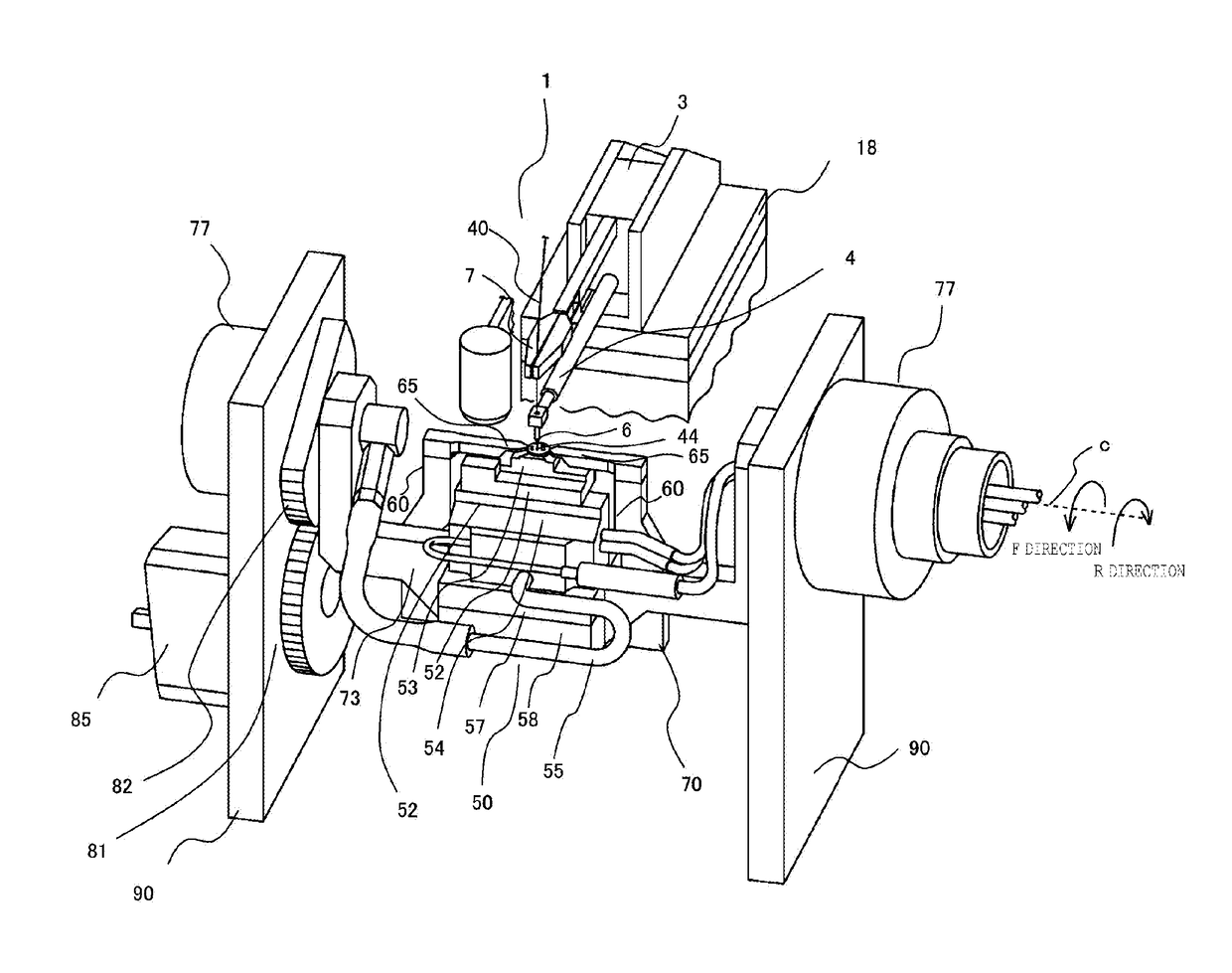
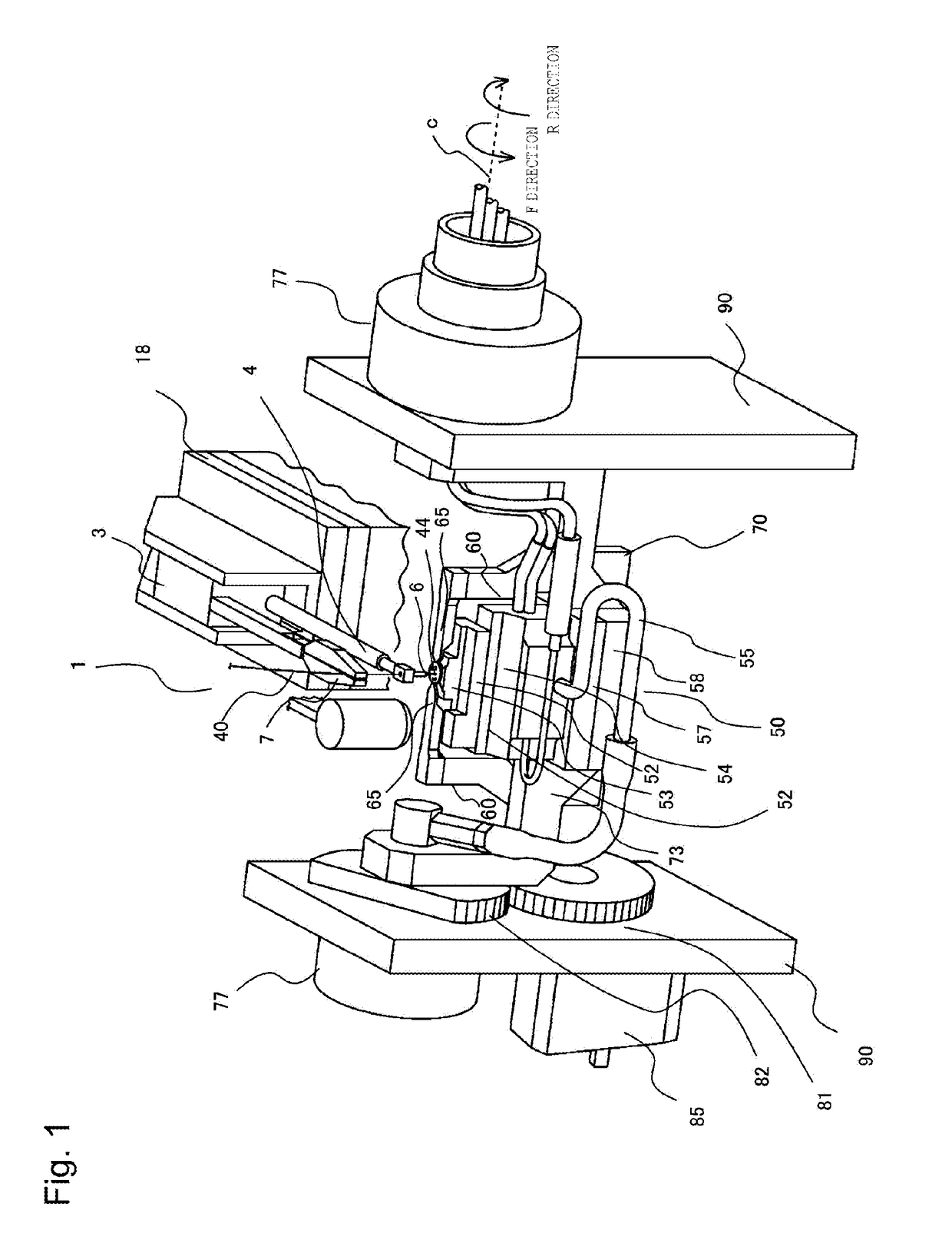
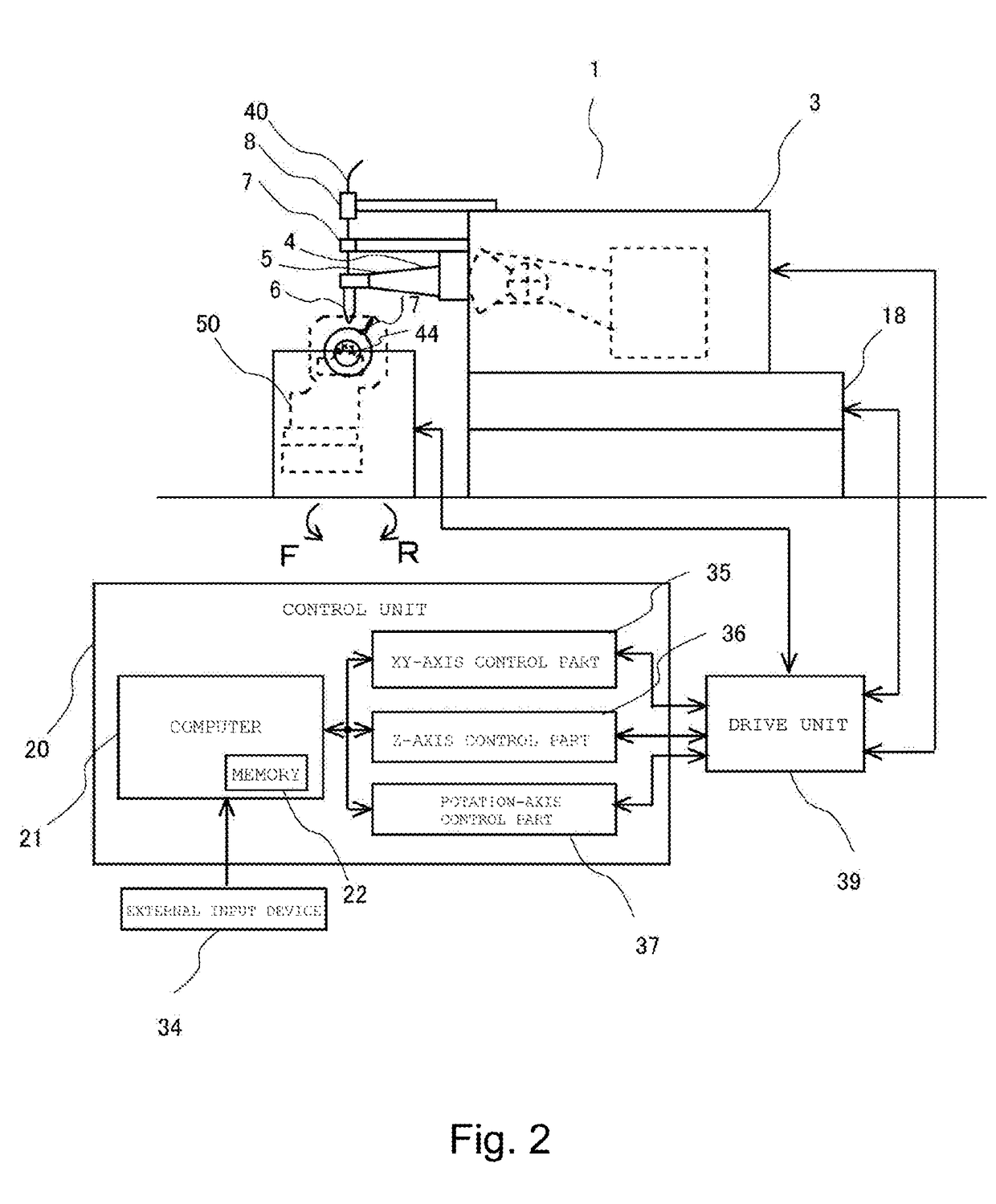
[0050]Hereinafter, embodiments of the bonding apparatus and the bonding method according to the present invention will be described by referring to the drawings. In the explanations below, a wire bonding apparatus which connects electrodes of an object to be bonded and a lead by using a wire is used for describing the bonding apparatus.

[0051]The present invention enables bonding by correcting a difference in separation distances of bonding positions of a plurality of bonding points with respect to a bonding head through controlling rotation of a work-holder in accordance with the difference in the separation distances of the bonding positions of the bonding object with respect to the bonding head as a bonding means. Further, the present invention also enables bonding by correcting the difference in the separation distances of the bonding positions when the distances on the bonding faces vary through controlling a rotary mechanism unit 70 (shown in FIG. 3) such that relative position...


PUM

PropertyMeasurementUnit
Distanceaaaaaaaaaa
Torqueaaaaaaaaaa

Abstract

Bonding processing for a plurality of bonding points of different distances with respect to a reference position (origin) of an object to be bonded without changing a moving distance of bonding means is provided. The bonding means, a bonding stage having a work-holder and a rotary mechanism unit for rotating the work-holder, and a control unit for controlling rotation of the work-holder are provided. The bonding means is movable relative to a placement surface of the work-holder in a reference orientation and has a reference position on its moving direction. The plurality of bonding points include bonding points of different separation distances from the reference position along the moving direction while the object to be bonded is being held to the work-holder in the reference orientation. The control unit corrects differences in the separation distances of the plurality of bonding points by controlling rotation of the work-holder.

Description

CROSS-REFERENCE TO RELATED APPLICATIONS[0001]This application is a U.S. National Stage of International Application No. PCT / JP2017 / 006583, filed on Feb. 22, 2017, and claims priority to Japanese Application No. 2016-110973, filed on Jun. 2, 2016, the entire disclosures of the above applications are incorporated herein by reference.BACKGROUNDTechnical Field[0002]The present invention relates to a bonding apparatus, a bonding method, and a bonding control program for bonding an object to be bonded having three or more bonding faces in different directions by using a wire or the like.Related Art[0003]Conventionally, known as a bonding apparatus is a wire bonding apparatus which connects an electrode (pad) on an IC chip as a first bonding point with a lead as a second bonding point by using a gold wire, a wire made of copper, or the like.[0004]In the wire bonding apparatus which performs bonding of the pad on the IC chip as the first bonding point with the lead of a lead frame made of a...

Claims


Application Information

Patent Timeline
IPC IPC(8): B23K20/10B23K20/26H01L23/00
CPCB23K20/10B23K20/26H01L24/78H01L24/85B23K2101/40H01L2224/78981H01L2224/78802H01L2224/78251H01L2224/78353H01L2224/78001H01L2224/78349H01L2224/85205H01L24/48H01L24/49H01L2224/78803H01L2224/859B23K20/00H01L21/52H01L21/67092H01L21/67103
Inventor KOMAGINO, YUJIYAMAGUCHI, HODAKAYOSHINO, HIDEKI
Owner KAIJOO KK
Why Eureka
Try Eureka