Simulation method for evaluating a golf club head

a golf club head and simulation method technology, applied in golf clubs, cad techniques, instruments, etc., can solve the problems of time-consuming and costly experimental evaluation based on actual physical prototypes, complex airflow turbulence around the body, and the inability to accurately evaluate the aerodynamic performance so as to efficiently develop a higher performance product, the time required to evaluate the shape of the golf club head is shortened, and the effect of increasing the accuracy and objectivity of the evaluation

Inactive Publication Date: 2014-08-12
BRIDGESTONE SPORTS
View PDF20 Cites 0 Cited by
  • Summary
  • Abstract
  • Description
  • Claims
  • Application Information

AI Technical Summary

Benefits of technology

[0030]With the simulation method for evaluating a club head according to the present invention, the aerodynamic forces which act upon the club head when a golf club is swung at a predetermined velocity can be estimated. Hence, a club head having a complex shape can be evaluated without relying on experimental evaluation using a physical prototype, thus enabling the “swing through” feel and the stability of the club head trajectory to be estimated and evaluated.
[0031]As a result, the time required to evaluate a club head shape is shortened, in addition to which the accuracy and objectivity of the evaluation are increased, thus making it possible to efficiently develop a higher performance product for the type and grade of club.BRIEF DESCRIPTION OF THE DIAGRAMS
[0032]FIG. 1 is a schematic perspective diagram illustrating a club head model and a virtual airflow region in the method of the invention.
[0033]FIG. 2 is a schematic diagram showing a cross-sectional view passing through the center of the club head model in FIG. 1.
[0034]FIG. 3 is a perspective view showing an example of a club head model in the invention.
[0035]FIG. 4 is a diagram showing specific examples of the shapes of grid cells formed in the virtual airflow region in the invention.

Problems solved by technology

It is known that when a physical body travels through the air at such a high speed, airflow turbulence arises around the body.
In this case, depending on the shape of the body, the turbulence of the air streams that flow around the body is complex and exerts a major influence on the motion of the body.
However, such experimental evaluation based on actual physical prototypes is time-consuming and costly, in addition to which it is difficult to arrive at a clear understanding of the aerodynamic properties from the resulting changes in air flow.
Moreover, establishing a clear causal relationship between the aerodynamic properties and the club head performance is not always easy.
Hence, club heads which have been newly designed based on evaluation results obtained by experimentation often fail to achieve the intended performance.
In such cases, it is necessary each time to design and test-produce a new club head and determine its aerodynamic properties, resulting in further outlays of time and expense, and thus making efficient club development impossible.

Method used


Image

  • Simulation method for evaluating a golf club head
  • Simulation method for evaluating a golf club head
  • Simulation method for evaluating a golf club head

Examples


example 1

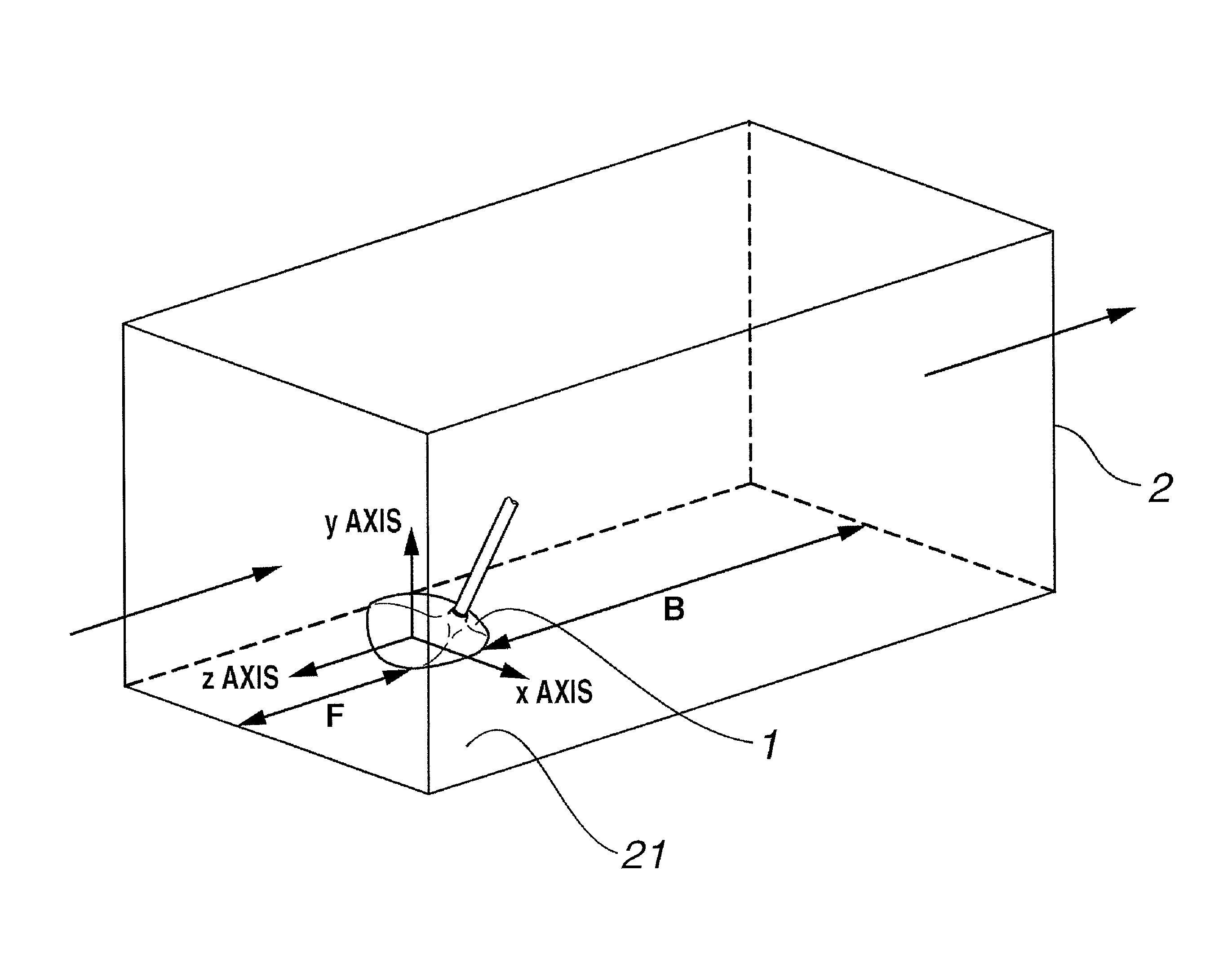
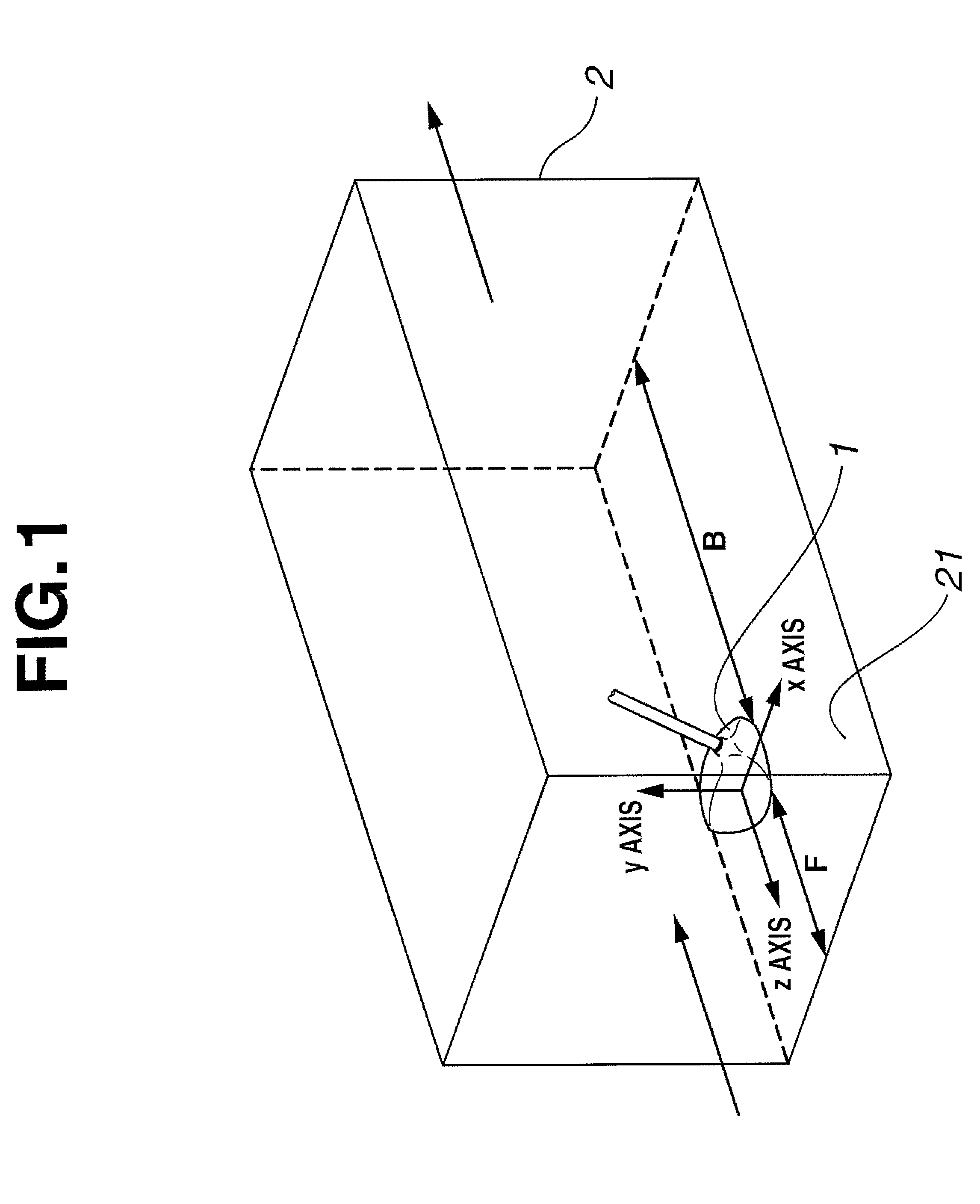
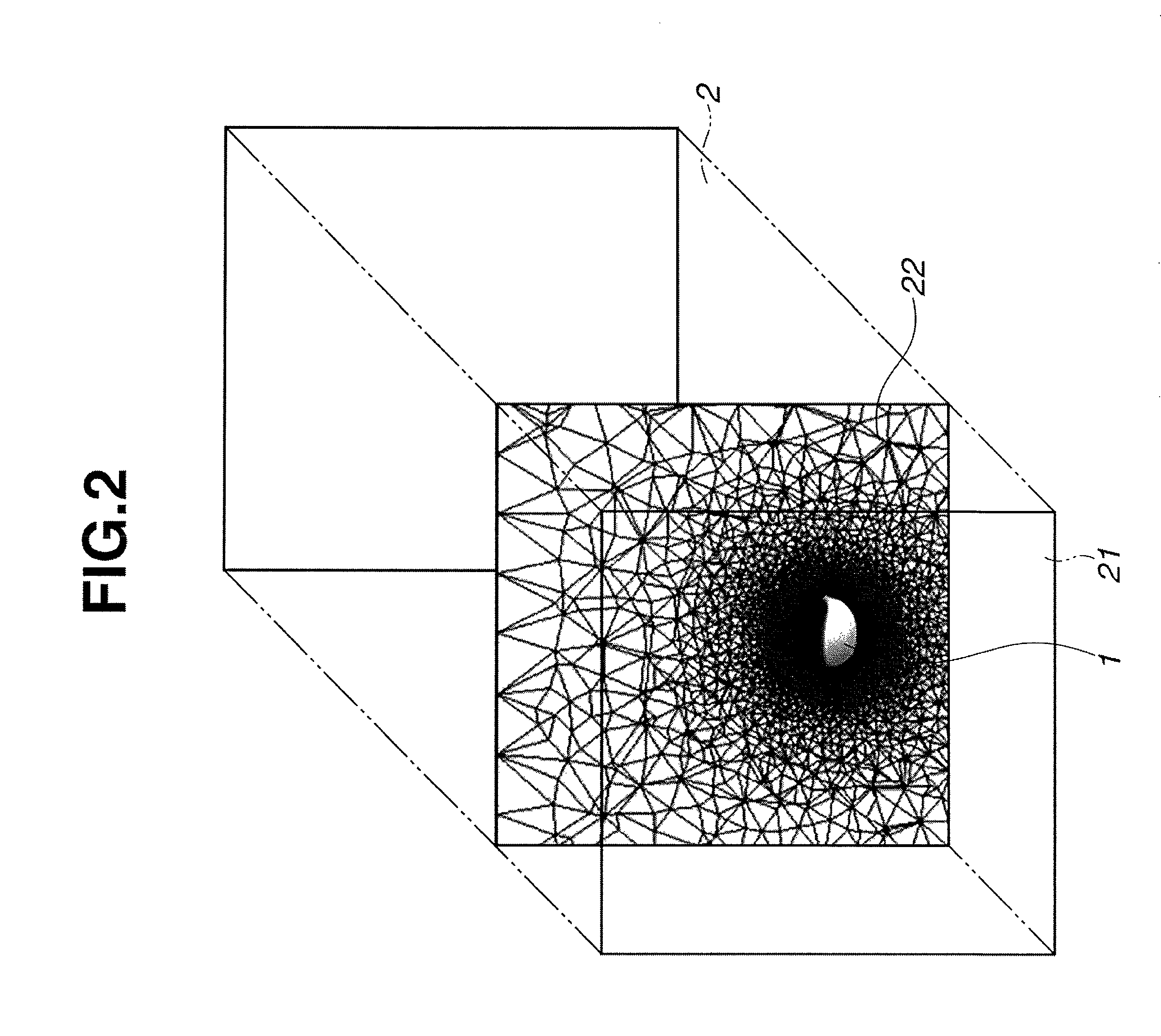
[0070]A virtual airflow region and a club head model similar to those shown in FIG. 1 were set up in a computer by setting up, within a virtual space created in a computer, a club head model of the shape shown in FIGS. 6 and 7 and a virtual airflow region surrounding the periphery of the club head model, and by also setting up, on a bottom side of the virtual airflow region, a wall representing a ground surface, thereby making the bottom side of the virtual airflow region a closed side, and setting the clearance between the club head model and the ground surface to 50 mm. The dimensions of the virtual airflow region were set as follows: the vertical and left / right dimensions were each set to 1 m, the length F in front of the club head model was set to 50 cm, and the length B in back of the club head model was set to 1 m. The left / right direction of the club head model was set as the x axis, the vertical direction of the club head model was set as the y axis, and the front / back direc...

example 2

[0074]Aside from setting the clearance between the club head model and the ground surface to 10 mm, the x-axis direction, y-axis direction and z-axis direction forces acting upon the club head model were calculated in the same way as in Example 1. The results are shown in the graph in FIG. 5. Also, as in Example 1, the distribution in pressure due to air flow around the club head model was visualized by isobaric lines or isobaric surfaces, or stream lines of the same air flow were visualized. FIG. 8 shows the pressure distribution, and FIG. 9 shows the stream lines.

Observations Concerning Examples 1 and 2

[0075]As shown in the graph in FIG. 5, the x-axis direction, y-axis direction and z-axis direction forces each vary depending on the clearance with the ground, confirming that it is possible with the simulation method of the invention to evaluate the aerodynamic performance of the club head by estimating the aerodynamic forces which act upon the club head when a golf club is swung. ...


PUM


Abstract

A simulation method for evaluating the aerodynamic performance of a golf club head uses arithmetic operations executed by a computer to analyze air flow around the head of a golf club when the club is swung, and thereby estimates the aerodynamic forces which act on the club head. Because the aerodynamic properties of a golf club head are evaluated without relying on experimental evaluations using physical prototypes, this method enables the efficient development of golf clubs.

Description

CROSS-REFERENCE TO RELATED APPLICATION[0001]This non-provisional application claims priority under 35 U.S.C. §119(a) on Patent Application No. 2010-287840 filed in Japan on Dec. 24, 2010, the entire contents of which are hereby incorporated by reference.TECHNICAL FIELD[0002]The present invention relates to a simulation method for evaluating the aerodynamic performance of a golf club head, which method uses arithmetic operations executed by a computer to analyze air flow around the head of a golf club when the club is swung and thereby estimates the aerodynamic forces which act on the club head.BACKGROUND ART[0003]When a golf club is swung, the head attached to the end of the club reaches a velocity of 40 to 50 m / s in the case of long clubs such as a driver. It is known that when a physical body travels through the air at such a high speed, airflow turbulence arises around the body. In this case, depending on the shape of the body, the turbulence of the air streams that flow around t...

Claims


Application Information

Patent Timeline
Patent Type & Authority Patents(United States)
IPC IPC(8): G06F17/50A63B69/36G06F7/60G06F17/10G06G7/48A63B53/00A63B53/04A63B102/32
CPCA63B69/3614G06F17/5018A63B2069/3605G06F17/5009G06F2217/16G06F2111/10G06F30/20G06F30/23A63B69/3605G06F30/28
Inventor BAN, WATARU
Owner BRIDGESTONE SPORTS
Why Eureka
Try Eureka