Backlight drive circuit, method for driving the same, and liquid crystal display device

Active Publication Date: 2016-08-25
TCL CHINA STAR OPTOELECTRONICS TECH CO LTD
View PDF6 Cites 2 Cited by
  • Summary
  • Abstract
  • Description
  • Claims
  • Application Information

AI Technical Summary

Benefits of technology

[0015]1. The backlight drive circuit proposed in the present disclosure comprises a plurality of backlight drive units, wherein each of the backlight drive units receives all of the pulse dimming signals, and electrically connected to an identical number of light emitting cells in all of the backlight partitions. When a pulse dimming signal is received, all of the backlight drive units supply power to drive said light emitting cells in a corresponding backlight partition to emit light. As a result, when the partitions are scanned, from top to bottom, in the liquid crystal panel on by one, each of the backlight drive units may undergo permanently a power outputting condition, so that the operating efficiency of the entire backlight drive circuit can be improved.
[0016]2. The backlight driving method provided in the present disclo

Problems solved by technology

In general, there are a very large number of LED strips in a large-sized liquid crystal display device, and the power consumed thereby is also considerably high.
Such an operating manner may lead to a localized high temperature in a backlight drive circuit, so that heat throughou

Method used


Image

  • Backlight drive circuit, method for driving the same, and liquid crystal display device
  • Backlight drive circuit, method for driving the same, and liquid crystal display device
  • Backlight drive circuit, method for driving the same, and liquid crystal display device

Examples


Example

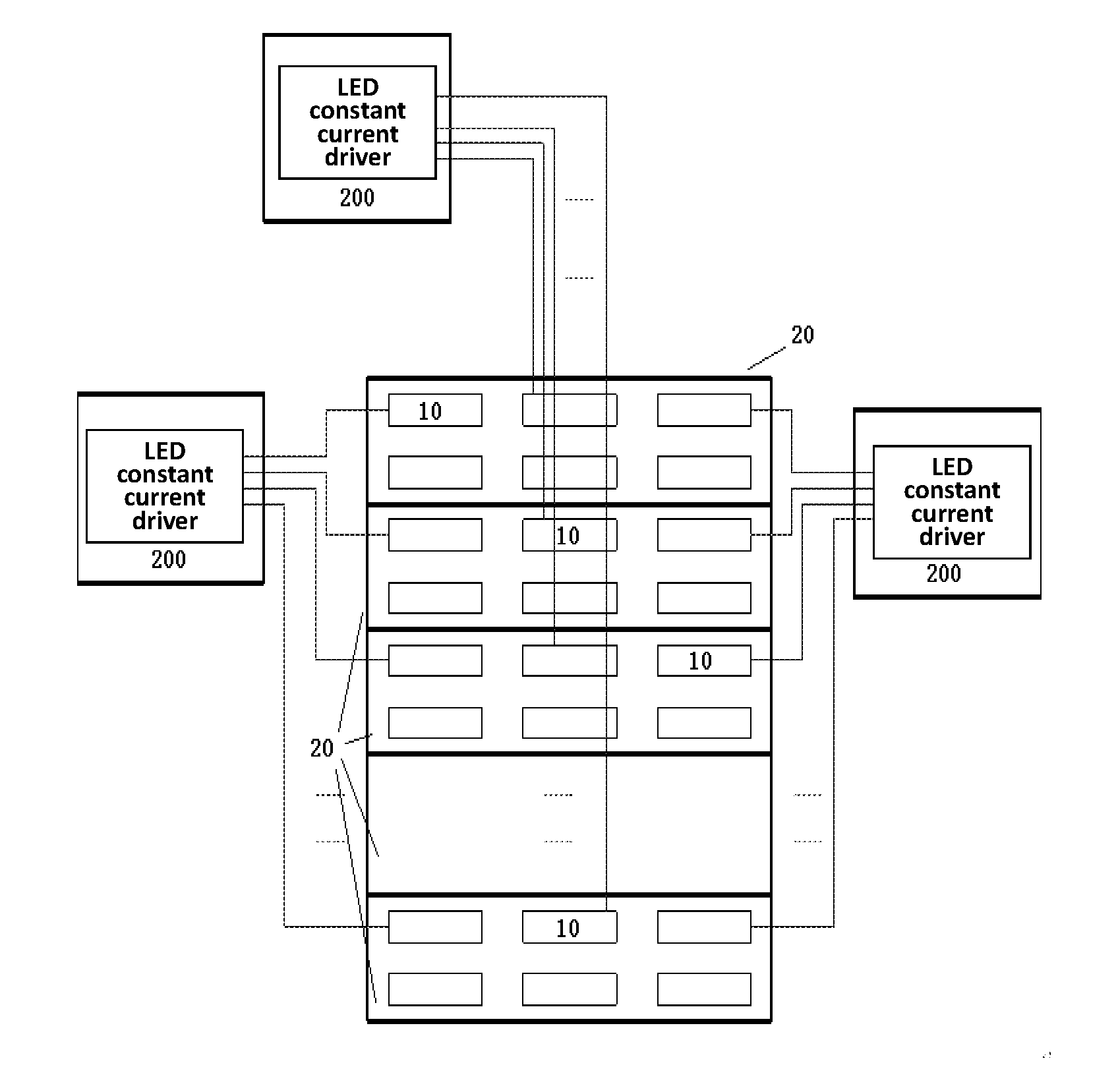
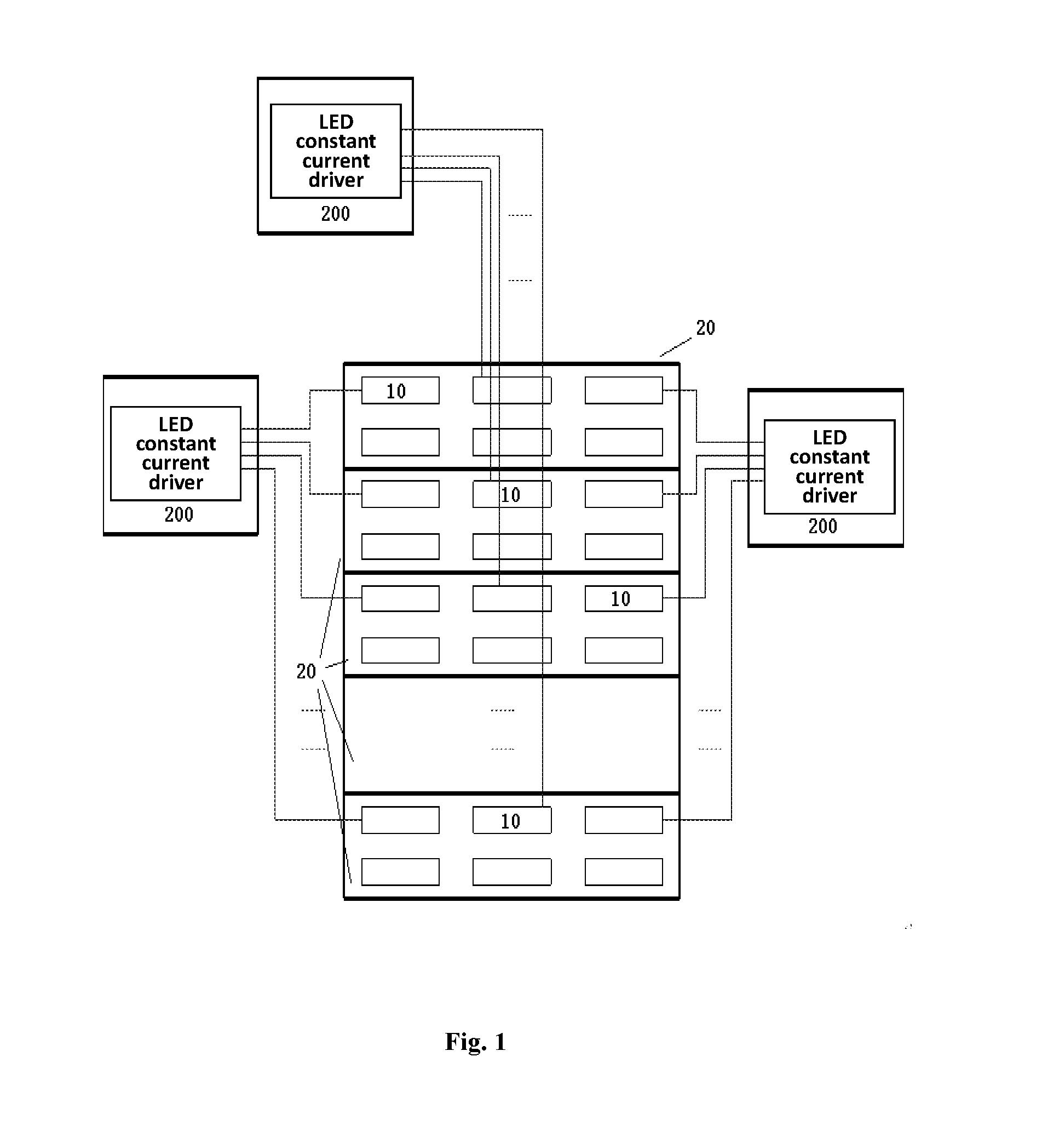
[0024]FIG. 1 is a structural diagram of a backlight drive circuit according to the present disclosure. As described above, a liquid crystal display panel using such a circuit for backlight driving may be, for example, a large-sized liquid crystal display panel which is based on LED backlight display technology. When such a large-sized liquid crystal display panel is operating in a three-dimensional scan mode, LED strips 10 may be divided, from top to bottom, into a plurality of backlight partitions 20, and all of the backlight partitions 20 contain an identical quantity of LED strips 10. During transmission of a three-dimensional image display signal, the backlight partitions may be lightened respectively in terms of transmission of the three-dimensional image display signal. A main idea of the technical solution provided by the present disclosure is that each backlight partition, whenever lightened, would be supplied with the power required for its lightening from all of the LED ba...


PUM


Abstract

Related to is a backlight drive circuit and a method for driving the backlight drive circuit, and a resulting liquid crystal display device. The backlight drive circuit comprises a plurality of light emitting cells divided into several backlight partitions in an even manner; pulse dimming signal units of a same number with the backlight partitions, each of the pulse dimming signal units outputting a pulse dimming signal; and a plurality of backlight drive units, each of which is electrically connected to all of the pulse dimming signal units to receive respective pulse dimming signals output by the pulse dimming signal units, and meanwhile each of which is further electrically connected to an identical number of light emitting cells in all of the backlight partitions. When a pulse dimming signal is output from a pulse dimming signal unit, all of the backlight drive units supply power to their respectively connected light emitting cells in a corresponding backlight partition, so as to drive said light emitting cells to emit light.

Description

COSS-REFERENCE TO RELATED APPLICATIONS[0001]The present application claims benefit of Chinese patent application CN 201410817656.2, filed on Dec. 24, 2014, and entitled “BACKLIGHT DRIVE CIRCUIT, METHOD FOR DRIVING THE SAME, AND LIQUID CRYSTAL DISPLAY DEVICE,” the entire disclosure of which is hereby incorporated by reference.FIELD OF THE INVENTION[0002]The present disclosure relates to a backlight driving technology for a liquid crystal display device, and in particular, to a backlight drive circuit applicable to a large-sized liquid crystal display device and a method for driving the large-sized liquid crystal display device, and a resulting liquid crystal display device.BACKGROUND OF THE INVENTION[0003]In general, there are a very large number of LED strips in a large-sized liquid crystal display device, and the power consumed thereby is also considerably high. When the large-sized liquid crystal display device operates in a three-dimensional scan mode, the LED strips, from top to...

Claims


Application Information

Patent Timeline
IPC IPC(8): H05B33/08G02F1/1335H05B44/00
CPCG02F1/133603G09G3/36G09G3/34H05B33/0815G09G3/003G09G3/3406G09G2310/024G09G2320/0233G09G2320/041G09G2320/064G09G2330/045H05B45/46H05B45/3725Y02B20/30H05B45/10
Inventor ZHANG, HUALI, FEI
Owner TCL CHINA STAR OPTOELECTRONICS TECH CO LTD
Why Eureka
Try Eureka