Commercial laundry machine with improved loading hopper

Inactive Publication Date: 2005-03-10
ELLIS AG
View PDF20 Cites 2 Cited by
  • Summary
  • Abstract
  • Description
  • Claims
  • Application Information

AI Technical Summary

Benefits of technology

[0009] It is an object of the present invention to provide a commercial laundry machine having a loading hopper designed to substantially reduce the loading time, and hence, substantially improve operating efficiency of the laundry machine. In this re

Problems solved by technology

Apart from the actual laundering cycles, i. e. for example, the washing and extract cycles, a substantial amount of time is consumed in loading large quantities of items to be laundered into the laundry machine.
Unfortunately, the prior art arrangement disclosed in the aforesaid '772 patent does not appreciably shorten the loading cycle time.
Moreover, since typically as many as six 200 pound slings of launderable items can be required to fill a commercial washer, sequencing of the slings to the unloading position and directing the items into the laundry machine can be very time consuming.
Use of loading hoppers in conventional commercial laundry machines, furthermore, has been problem prone.
Items introduced into the hopper during loading can catch upon or fall behind the splash door, which can impede its operation.
Items also can hang up in the hopper and the splash door if water is not continually sprayed down the hopper to assist in moving the items into the drum, which can result in raising the liquid within the drum above the programmed level and necessitate a drainage cycle prior to start of washing.
Moreover, during the extract cycle of operation, i. e. the high speed spin cycle that forces liquid from laundered items following a wash cycle, the machine can experience extensive vibrations, particularly if the laundry load becomes out of balance.
Indeed, during the extract cycle, items rotating within the laundry machine can be exposed to forces up to 300 times gravity, While it is known to support the laundry machine on inflated bags during the extract cycle for better isolating the machine from the floor, since the hopper is mounted on the laundry machine, it still can be subjected to su

Method used


Image

  • Commercial laundry machine with improved loading hopper
  • Commercial laundry machine with improved loading hopper
  • Commercial laundry machine with improved loading hopper

Examples


Example

[0033] While the invention is susceptible of various modifications and alternative constructions, a certain illustrative embodiment thereof has been shown in the drawings and will be described below in detail. It should be understood, however, that there is no intention to limit the invention to the specific form disclosed, but on the contrary, the intention is to cover all modifications, alternative constructions, and equivalents falling within the spirit and scope of the invention.

DETAILED DESCRIPTION OF THE PREFERRED EMBODIMENT

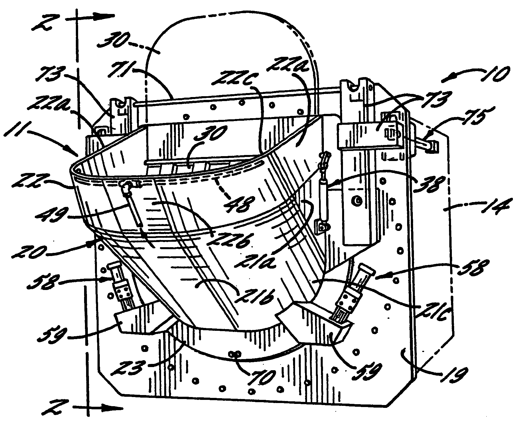
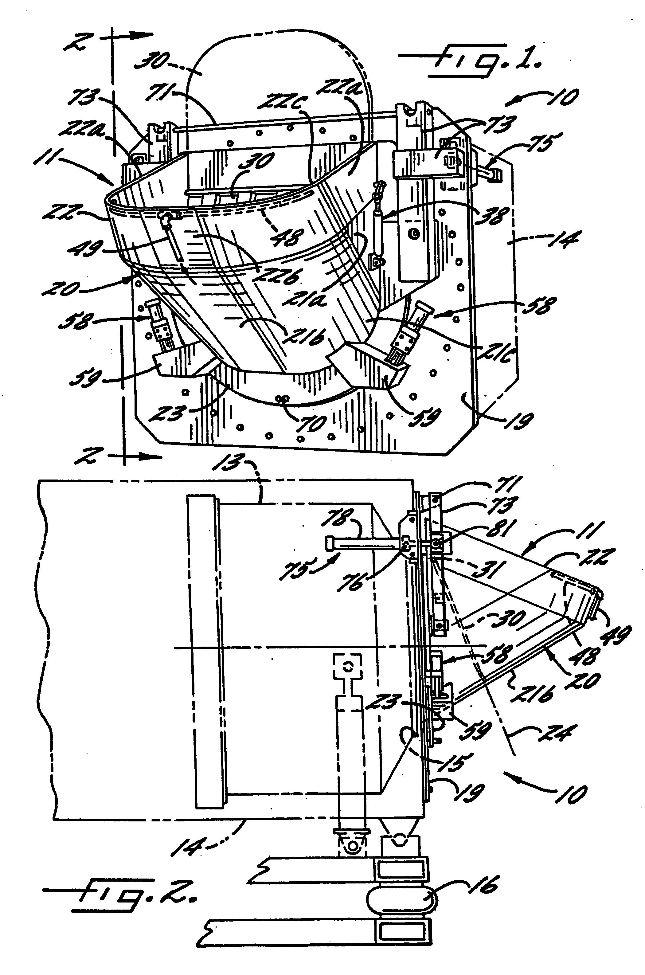
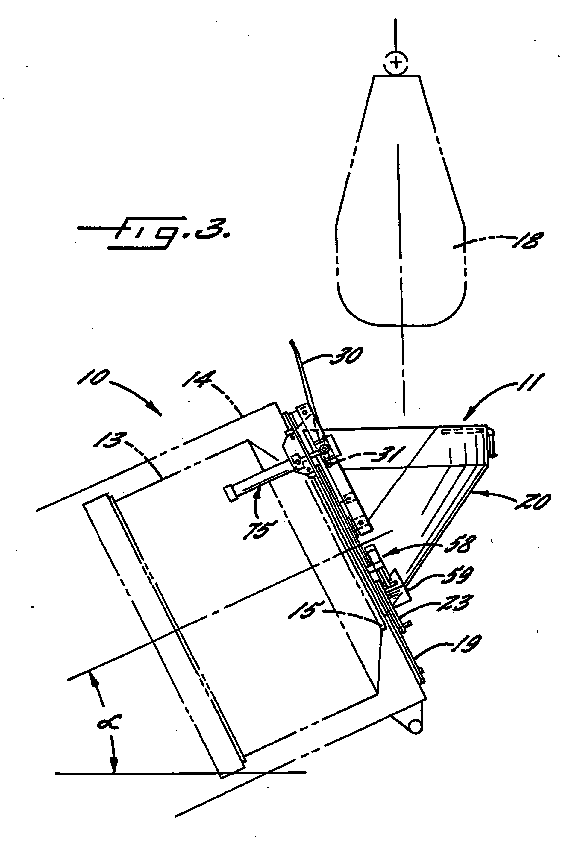
[0034] Referring now more particularly to the drawings, there is shown an illustrative commercial laundry machine 10 having a loading hopper unit 11 embodying the present invention. The laundry machine 10 includes a conventional drum 13 that is rotatably mounted within a machine housing 14 and has a front opening 15, through which launderable items are introduced into the drum 13 for laundering. As is known in the art, the housing 14 and drum 13 are adapt...


PUM


Abstract

A commercial laundry machine having a loading hopper effective for substantially reducing loading time. The hopper has a relatively large effective passage area for communication with a front opening rotary drum of the laundry machine, and a splash door is pivotally mounted adjacent a front face of the machine housing for movement between a lowered closed position and an upwardly extending open position which neither reduces the effective passage of the hopper chute nor impedes the passage of launderable items directed through the chute. The laundry machine further includes an improved toggle actuated locking and sealing device for securing the hopper in sealed relation with the machine housing, and trunnion mounted hydraulic cylinders which are effective for more reliably and effectively pivoting the hopper unit through an arc greater than 90 degrees to its removed position.

Description

FIELD OF THE INVENTION [0001] The present invention relates generally to commercial / industrial washing, drying, dyeing and like laundry machines, and more particularly, to a commercial laundry machine having a hopper that facilitates loading of launderable items into the machine prior to a laundry cycle. BACKGROUND OF THE INVENTION [0002] Commercial / industrial laundry machines typically are large in size (i. e., 100 to 1200 pound in capacity)for laundering large amounts of items simultaneously. Apart from the actual laundering cycles, i. e. for example, the washing and extract cycles, a substantial amount of time is consumed in loading large quantities of items to be laundered into the laundry machine. As will be appreciated, the time consumed in loading the laundry machine restricts the actual operating time. Thus, the time associated with loading the laundry machine has a significant impact on the operational efficiency of the commercial laundry facility. [0003] One common method ...

Claims


Application Information

Patent Timeline
IPC IPC(8): D06F95/00
CPCD06F95/00
Inventor SHAW, JAMES M.KROEGER, MICHAEL T.
Owner ELLIS AG
Why Eureka
Try Eureka