Air conditioner

a technology for air conditioners and fans, applied in the field of air conditioners, can solve the problems of increasing the flow speed of air currents blown out of outlets, increasing drafts, etc., and achieve the effect of facilitating passageways

Active Publication Date: 2006-12-07
DAIKIN IND LTD
View PDF11 Cites 48 Cited by
  • Summary
  • Abstract
  • Description
  • Claims
  • Application Information

AI Technical Summary

Benefits of technology

[0017] With this air conditioner, it is even easier to ensure passageways, between each corner part outlet and the side part outlets adjacent to that corner part outlet, for the air sucked into the inlet.

Problems solved by technology

Furthermore, when this type of an air conditioner operates, the air inside the air conditioned room flows from the space below the inlet toward the inlet and is sucked inside the casing through the inlet.
In contrast, it is conceivable to reduce the number of outlets by increasing the space between the outlets, reducing the opening area of the outlets, and the like; however, doing so will increase the flow speed of the air currents blown out from the outlets, thereby increasing drafts.

Method used


Image

  • Air conditioner
  • Air conditioner
  • Air conditioner

Examples


Embodiment Construction

[0048] The following explains the embodiments of an air conditioner according to the present invention, referencing the drawings.

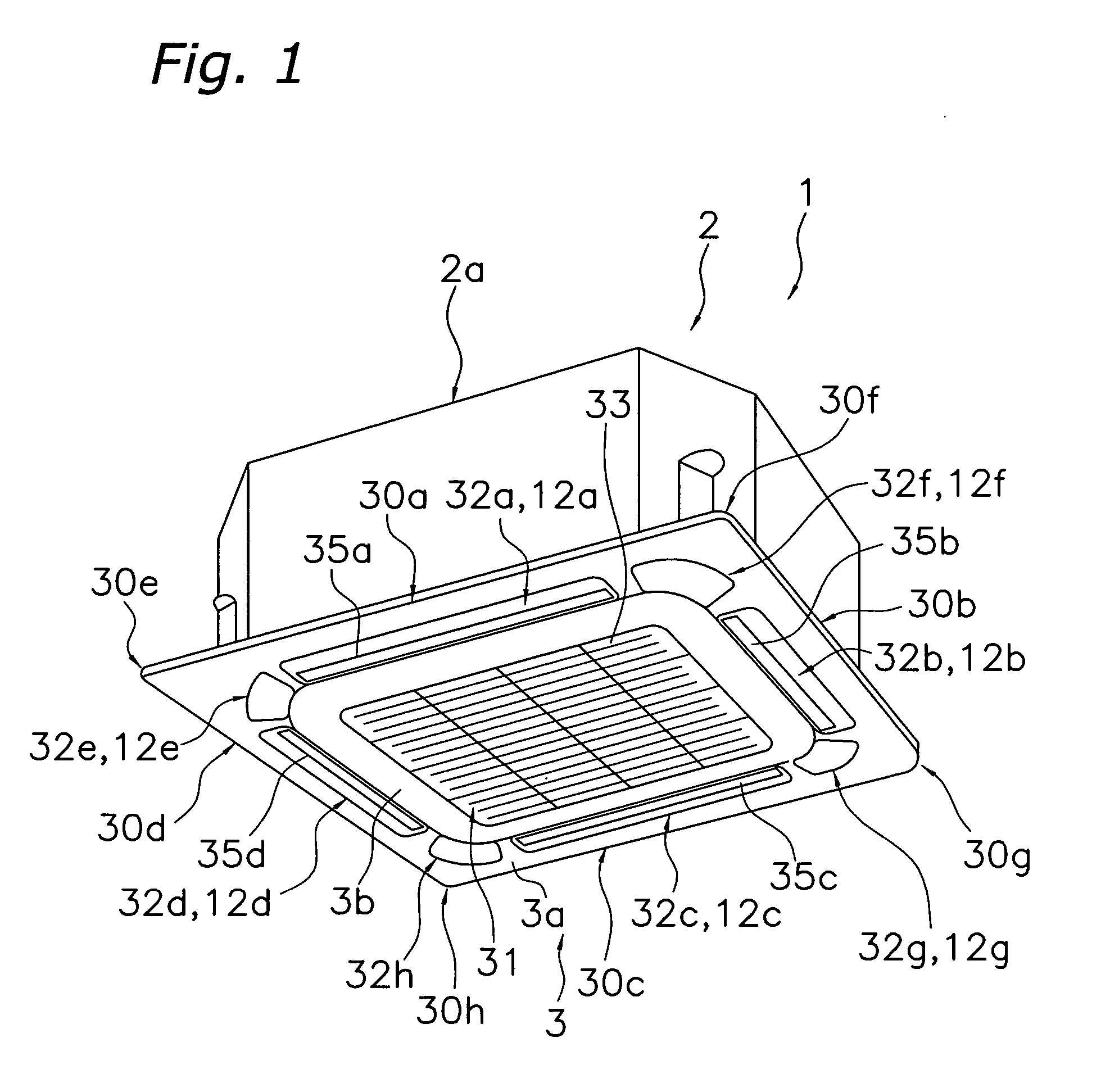
(1) Basic Constitution of the Air Conditioner

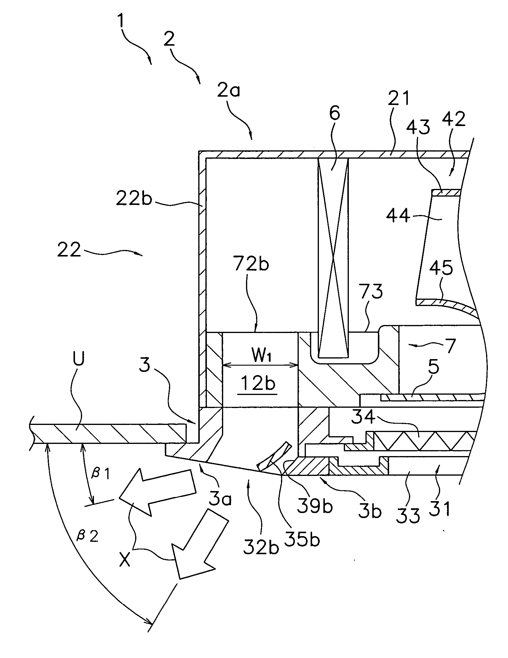
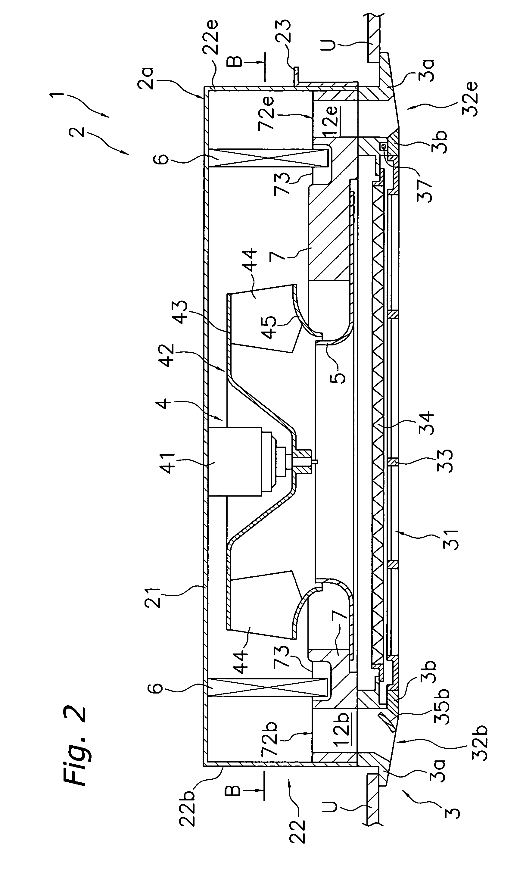
[0049]FIG. 1 is an external perspective view of an air conditioner 1 according to one embodiment of the present invention (ceiling is not shown). The air conditioner 1 is a ceiling embedded type air conditioner, and comprises a casing 2 that internally houses various constituent equipment. The casing 2 comprises a casing main body 2a, and a face panel 3 disposed on the lower side of the casing main body 2a. As shown in FIG. 2, the casing main body 2a is disposed inserted into an opening formed in a ceiling U of the air conditioned room. Furthermore, the face panel 3 is disposed so that it is fitted into the opening of the ceiling U. Here, FIG. 2 is a schematic side cross sectional view of the air conditioner 1, and is a cross sectional view taken along the A-O-A line in FIG. 3.

[0050] As shown in FIG. 2 and FI...


PUM


Abstract

A ceiling embedded type air conditioner that reduces short circuits without increasing drafts due to air currents blown out from outlets includes a casing and a fan. The casing includes a casing lower part formed by an alternating sequence of four panel side parts and four panel corner parts. The casing further includes four main outlet passageways along the panel side parts auxiliary outlet passageways in the three panel corner parts and an inlet so that is surrounded by all of the panel side parts. The auxiliary outlet passageways are formed so that the spacing between each auxiliary outlet passageways and a corresponding adjacent main outlet passageways satisfies a prescribed dimensional relationship.

Description

FIELD OF THE INVENTION [0001] The present invention relates to an air conditioner, and more particularly relates to an air conditioner installed so that it is embedded in the ceiling of an air conditioned room. RELATED ART [0002] A so-called conventional ceiling embedded type air conditioner installed so that it is embedded in the ceiling of an air conditioned room principally comprises: a casing having a casing lower part formed by an alternating sequence of a plurality of side parts and a plurality of corner parts; outlets disposed so that each runs along a side part and an inlet disposed so that it is surrounded by the side parts; and a fan and a heat exchanger disposed inside the casing. [0003] Furthermore, when this type of an air conditioner operates, the air inside the air conditioned room flows from the space below the inlet toward the inlet and is sucked inside the casing through the inlet. Then, the heat of the air sucked into the casing is exchanged by the heat exchanger,...

Claims


Application Information

Patent Timeline
Patent Type & Authority Applications(United States)
IPC IPC(8): F24F13/06F24F1/00F24F13/14F24F13/20F24F13/32
CPCF24F1/0011F24F2001/0037F24F13/20F24F13/1413F24F1/0047
Inventor SANAGI, TSUNEHISATERAKAWA, AZUMISAKASHITA, AKIHIKO
Owner DAIKIN IND LTD
Why Eureka
Try Eureka