Ultrasonic transducer element chip, probe, electronic instrument, and ultrasonic diagnostic device

a transducer element and ultrasonic technology, applied in the direction of ultrasonic/sonic/infrasonic diagnostics, instruments, mechanical vibration separation, etc., can solve the problems of insufficient strength with respect to force in a thickness direction of the substrate, concern for deterioration of so as to reliably avoid damage to the ultrasonic transducer element, the effect of strengthening the strength of the substra

Active Publication Date: 2013-10-03
SEIKO EPSON CORP
View PDF6 Cites 35 Cited by
  • Summary
  • Abstract
  • Description
  • Claims
  • Application Information

AI Technical Summary

Benefits of technology

[0007]According to at least one embodiment of the present invention, an ultrasonic transducer element chip that is thin and has sufficient strength in resistance to pressing force in a thickness direction of a substrate can be provided.
[0009]In this kind of ultrasonic transducer element chip, the ultrasonic transducer elements can be formed to be thin. The ultrasonic transducer elements can be formed in a thin substrate. Even in a case where the reinforcing member is fixed to a substrate, the ultrasonic transducer element chip can be formed to be thin. In addition, since the reinforcing member is fixed on the second surface of the substrate, it is possible for the strength of the substrate to be reinforced in the substrate thickness direction. At this time, the internal spaces of the openings are in communication with the external space of the substrate. Ventilation is ensured between the internal spaces of the openings and the external space of the substrate. Therefore, the internal spaces of the openings are not sealed tight. The internal spaces of the openings can easily follow ambient pressure fluctuations. In this way, it is possible to reliably avoid damage to the ultrasonic transducer element. If by chance the internal spaces of the openings are sealed airtight, there will be concern for damage to the ultrasonic transducer element due to pressure fluctuations.
[0010]The reinforcing member may be bonded to a partition wall section of the substrate between the openings in at least one bonding region. When the partition wall section is bonded to the reinforcing member, the movement of the partition wall section is restricted by the reinforcing member. Thus, vibration of the partition wall section can be prevented. As a result, crosstalk between the ultrasonic transducer elements can be prevented. Further, when the movement of the partition wall section is restricted, it is possible to avoid having the vibration of the partition wall section act on the ultrasonic vibration of the ultrasonic transducer elements. Then, ultrasonic vibration in a clear vibration mode can be obtained in the ultrasonic transducer elements. Consequently, when vibration of the partition wall section is avoided in this way, it is possible to inhibit a decrease in the amplitude of ultrasonic vibration.
[0011]The reinforcing member may include a first surface overlaid on the second surface of the substrate, and the ventilation passage includes a plurality of groove parts formed on the first surface of the reinforcing member. In this way, it is possible to ensure a ventilation passage relatively easily.
[0012]The ventilation passage may include a plurality of groove parts formed on the second surface of the substrate. In this way, it is possible to ensure a ventilation passage relatively easily.
[0013]At least a portion of one of the substrate and the reinforcing member may be made of a porous material, and the ventilation passage may include a plurality of pores of the porous material. In this way, it is possible to ensure a ventilation passage relatively easily.

Problems solved by technology

When the openings are formed in the substrate, the strength of the substrate is deteriorated.
The strength is insufficient with respect to force in a thickness direction of the substrate.
If by chance the internal spaces of the openings are sealed airtight, there will be concern for damage to the ultrasonic transducer element due to pressure fluctuations.

Method used


Image

  • Ultrasonic transducer element chip, probe, electronic instrument, and ultrasonic diagnostic device
  • Ultrasonic transducer element chip, probe, electronic instrument, and ultrasonic diagnostic device
  • Ultrasonic transducer element chip, probe, electronic instrument, and ultrasonic diagnostic device

Examples


first embodiment

(2) Configuration of Ultrasonic Transducer Element Chip of First Embodiment

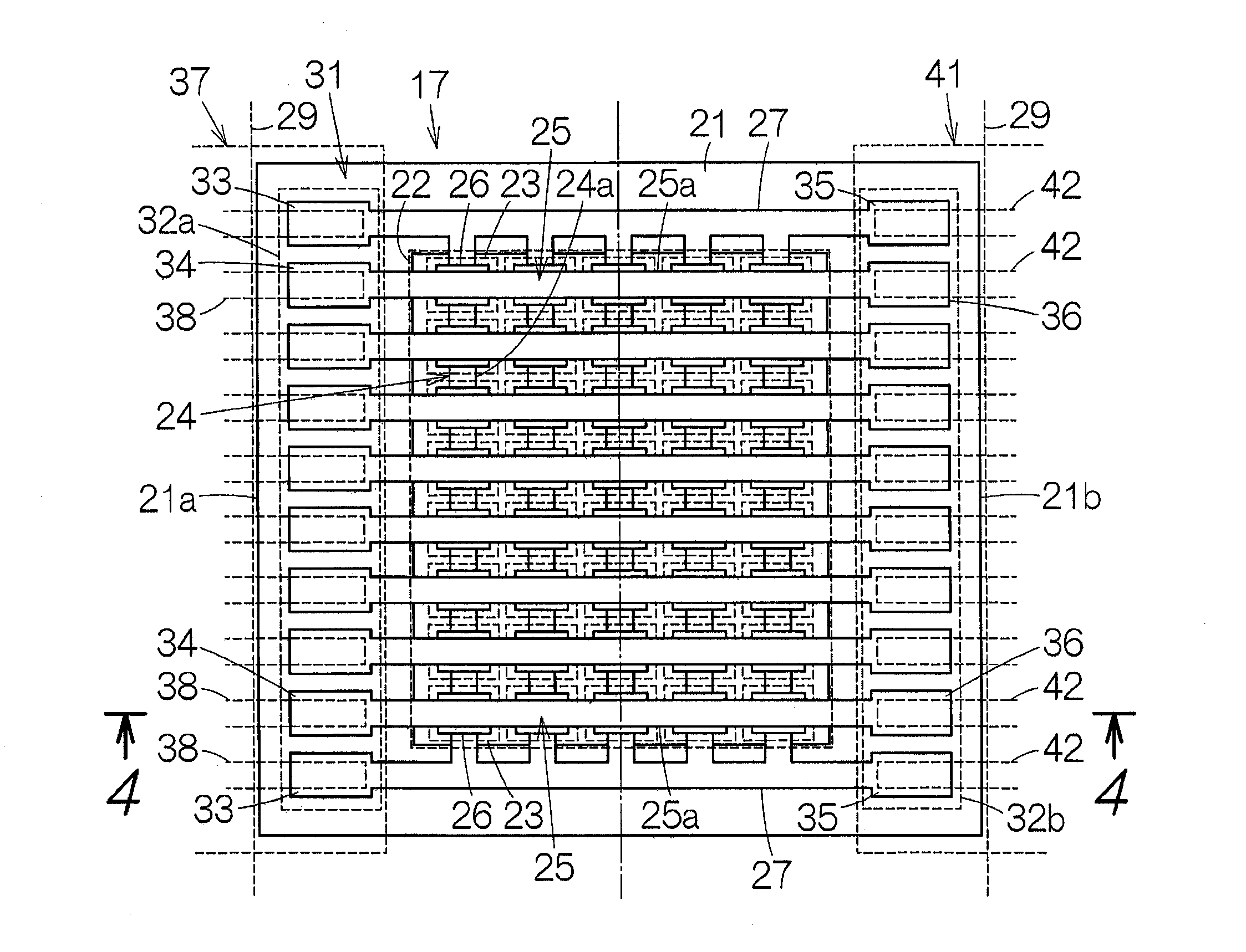
[0037]FIG. 3 schematically shows a plan view of the element chip 17 of the first embodiment. The element chip 17 is provided with a substrate 21. An element array 22 is formed on a surface (first surface) of the substrate 21. The element array 22 is constructed with an arrangement of ultrasonic transducer elements (hereinafter referred to as “elements”) 23. The arrangement is formed in a matrix having a plurality of rows and a plurality of columns. Each element 23 has a piezoelectric element section. The piezoelectric element section is constructed of a lower electrode 24, an upper electrode 25, and a piezoelectric film 26. The piezoelectric film 26 is sandwiched between the lower electrode 24 and the upper electrode 25 in each element 23.

[0038]The lower electrode24 has a plurality of first conductive bodies 24a. The first conductive bodies 24a extend in a column direction of the arrangement in parallel to ea...

second embodiment

(6) Ultrasonic Transducer Element Chip of Second Embodiment

[0069]FIG. 12 schematically shows the ultrasonic transducer element chip 17a of the second embodiment. With this element chip 17a, a plurality of groove (groove parts) 86 are arranged on the reverse surface of the substrate 21. The grooves 86 divide the reverse surface of the substrate 21 at the bottom edge of the partition wall 51 into a plurality of planes 87. The plurality of planes 87 expand within one hypothetical plane HP. The surface of the reinforcing plate 52 expands within that hypothetical plane HP. The grooves 86 sink from the hypothetical plane HP. The cross section shape of the groove 86 can be a quadrangle, a triangle, a semi-circle or another shape. As shown in FIG. 13, the grooves 86 between the planes 87 form the ventilation passages 88a, 88b between the substrate base 44 and the reinforcing plate 52. In this way, the spaces within the grooves 86 are connected to the spaces within the openings 45. The venti...

third embodiment

(7) Ultrasonic Transducer Element Chip of Third Embodiment

[0071]FIG. 15 schematically shows the ultrasonic transducer element chip 17b of the third embodiment. With this element chip 17b, at least a portion of one of the substrate 21 and the reinforcing plate 52 is constituted using a porous material. This kind of porous material is arranged at least between the openings 45 and between the opening 45 of the line end and the outer edge of the substrate 21. Here, the reinforcing plate 52 is formed from the porous material. The pores of the porous material are mutually and continuously lined so as to form the ventilation passages. The remainder of the constitution can be constituted in the same manner as the element chip 17. In the drawing, equivalent constitutions and structures to those of the element chip 17 are given the same reference code numbers.

[0072]While the present embodiment has been explained in detail as above, it will be apparent to those skilled in the art that various ...


PUM


Abstract

An ultrasonic transducer element chip includes a substrate, a plurality of ultrasonic transducer elements, a reinforcing member and a ventilation passage. The substrate defines a plurality of openings arranged in an array pattern. The ultrasonic transducer elements are respectively disposed at the openings on a first surface of the substrate. The reinforcing member is fixed on a second surface of the substrate opposite to the first surface of the substrate to reinforce the substrate. Through the ventilation passage, internal spaces of the openings and an external space of the substrate are in communication with each other.

Description

CROSS-REFERENCE TO RELATED APPLICATIONS[0001]This application claims priority to Japanese Patent Application No. 2012-078672 filed on Mar. 30, 2012. The entire disclosure of Japanese Patent Application No. 2012-078672 is hereby incorporated herein by reference.BACKGROUND[0002]1. Technical Field[0003]The present invention relates to an ultrasonic transducer element chip, a probe that uses the ultrasonic transducer element chip, and an electronic instrument and an ultrasonic diagnostic device and the like that use the probe.[0004]2. Related Art[0005]As described in Japanese Laid-Open Patent Publication No. 2011-82624, for example, an ultrasonic transducer element chip is provided with a substrate. A plurality of openings are formed in the substrate. An ultrasonic transducer element is provided in each of the openings. The ultrasonic transducer element is provided with a vibrating film. The vibrating film covers the openings from a surface of the substrate.SUMMARY[0006]When the opening...

Claims


Application Information

Patent Timeline
Patent Type & Authority Applications(United States)
IPC IPC(8): B06B1/06G03B42/06
CPCG03B42/06B06B1/0622A61B8/4494A61B8/00H04R17/00A61B8/4427H10N30/01H10N30/1071A61B8/4444A61B8/461A61B8/5207B06B1/0629G01S15/8934
Inventor NAKAMURA, TOMOAKITSURUNO, JIROKIYOSE, KANECHIKA
Owner SEIKO EPSON CORP
Why Eureka
Try Eureka