Locking system for air intake structure for turbojet engine nacelle

Inactive Publication Date: 2011-01-20
AIRCELLE
View PDF11 Cites 31 Cited by
  • Summary
  • Abstract
  • Description
  • Claims
  • Application Information

AI Technical Summary

Benefits of technology

[0030]Also advantageously, the control member is a handle, preferably retrac

Problems solved by technology

The assembly of these various elements (mobile cowls, case, air intake lip, outer shroud, acoustic panel) creates many aerodynamic breaks due to the presence of offsets and gaps between these elements inherent to their fastening together.
Moreover, the mobile cowls are mounted on hinges, also generating aerodynamic disturbances.
Such a locking s

Method used


Image

  • Locking system for air intake structure for turbojet engine nacelle
  • Locking system for air intake structure for turbojet engine nacelle
  • Locking system for air intake structure for turbojet engine nacelle

Examples


second embodiment

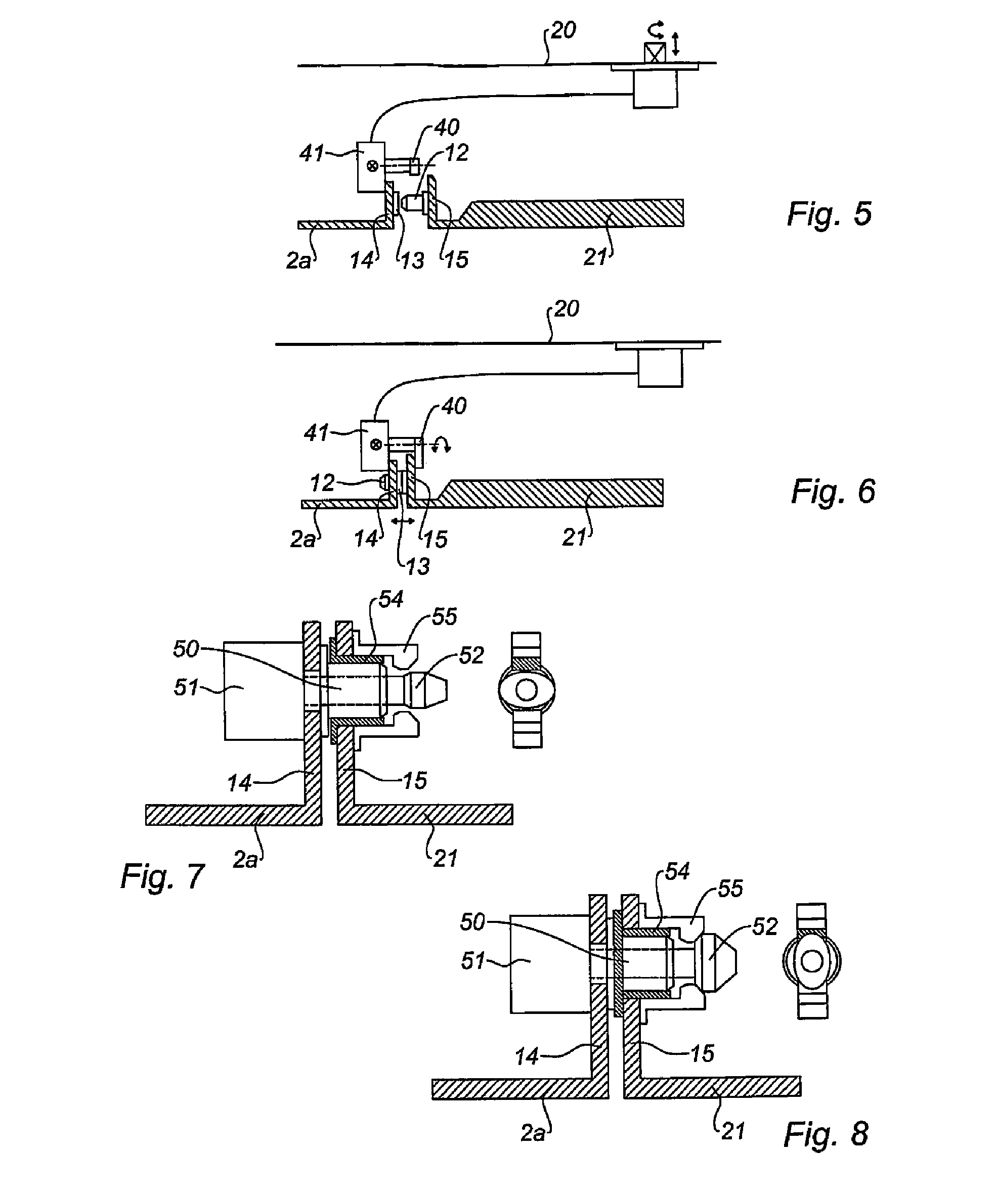
[0068]FIGS. 5 and 6 present the locking comprising a rotating hook 40 driven by an electric motor 41 capable of engaging with the return 15 of the inner panel 21, which then serves as complementary retaining means.

[0069]The centering pins can also be used directly in the locking means.

third embodiment

[0070]Thus, FIGS. 7 and 8 show a third embodiment in which the centering pin 50 is passed through by a blocking cam 52 capable of being driven in rotation by an electric motor 51 supported by the return 14 of the air intake structure 2a.

[0071]The pin 50 is capable of cooperating with a bore 54 formed in the return 15 of the inner panel 21.

[0072]The return 21 also supports retaining means 55 of the cam 52 designed such that said cam 52 has an unblocking position in which it can be removed from the retaining means 55 through the bore 54 and a blocking position in which it abuts against the retaining means 55, which then prevent its removal.

[0073]Of course, the cam 52 can be an integral part of the pin 50, which is then itself driven in rotation. Advantageously, the pin shall, however, be kept fixed in rotation.

[0074]FIGS. 9 and 10 present a screw locking system.

[0075]To do this, the return 15 of the inner panel 21 supports a threaded centering pin 60 capable of being driven in rotati...


PUM


Abstract

The invention relates to a nacelle for a turbojet engine that comprises an air intake structure (2) capable of directing an air flow towards a fan of the turbojet engine, and an intermediate structure for surrounding said fan and to which the air intake structure is attached in order to ensure aerodynamic continuity, wherein the air intake structure includes, on the one hand, at least one inner panel (21) attached to the intermediate structure and defining with the latter a fixed nacelle structure and, on the other hand, at least one longitudinal outer panel (20) removably attached to the fixed structure and including an air intake lip (2a) in order to form a removable air intake structure, characterised in that the air intake structure is provided with peripheral locking means including at least one locking means (10) attached to the inner panel or to the air intake lip and each capable of interacting with an additional retaining means (11) respectively attached to the air intake lip or to the inner panel.

Description

TECHNICAL FIELD[0001]The present invention concerns a locking device for a translatable air intake structure equipping a turbojet engine nacelle.BACKGROUND[0002]An airplane is propelled by one or several propeller assemblies comprising a turbojet engine housed in a tubular nacelle. Each propeller assembly is attached to the airplane by a mast situated generally under a wing or at the fuselage.[0003]A nacelle generally has a structure comprising an air intake upstream from the engine, a middle section designed to surround a fan of the turbojet engine, and a downstream section intended to surround the combustion chamber of the turbojet engine and housing thrust reverser means.[0004]The air intake comprises, on one hand, an intake lip adapted to allow optimal collection toward the turbojet engine of the air necessary to supply the fan and the internal compressors of the turbojet engine, and on the other hand, a downstream structure on which the lip is attached and designed to suitably ...

Claims


Application Information

Patent Timeline
IPC IPC(8): F04D29/40
CPCB64D29/06B64D29/08F02C7/042B64D2033/0286B64D2033/0206
Inventor VAUCHEL, GUY BERNARDDAUGUET, JEAN-PHILIPPEBEILLIARD, STEPHANE
Owner AIRCELLE
Why Eureka
Try Eureka