Communication apparatus, switching method, and switching program
Inactive Publication Date: 2006-12-07
PANASONIC CORP
View PDF8 Cites 27 Cited by
Summary
Abstract
Description
Claims
Application Information
AI Technical Summary
This helps you quickly interpret patents by identifying the three key elements:
Problems solved by technology
Method used
Benefits of technology
[0027] According to this construction, the data which was in the middle of transmission when switching from d
Problems solved by technology
In a small appliance such as a portable terminal (e.g. a PDA), however, it is difficult to install the two ports due to a limited installation space.
This technique however, has the following problem.
According to the above technique of supporting both data transfer methods by sharing the USB cable, it is impossible for the communication apparatus to recognize the USB connection using b
Method used
Image
Click on the blue label to locate the original text in one second.
Reading with bidirectional positioning of images and text.
Examples
Example
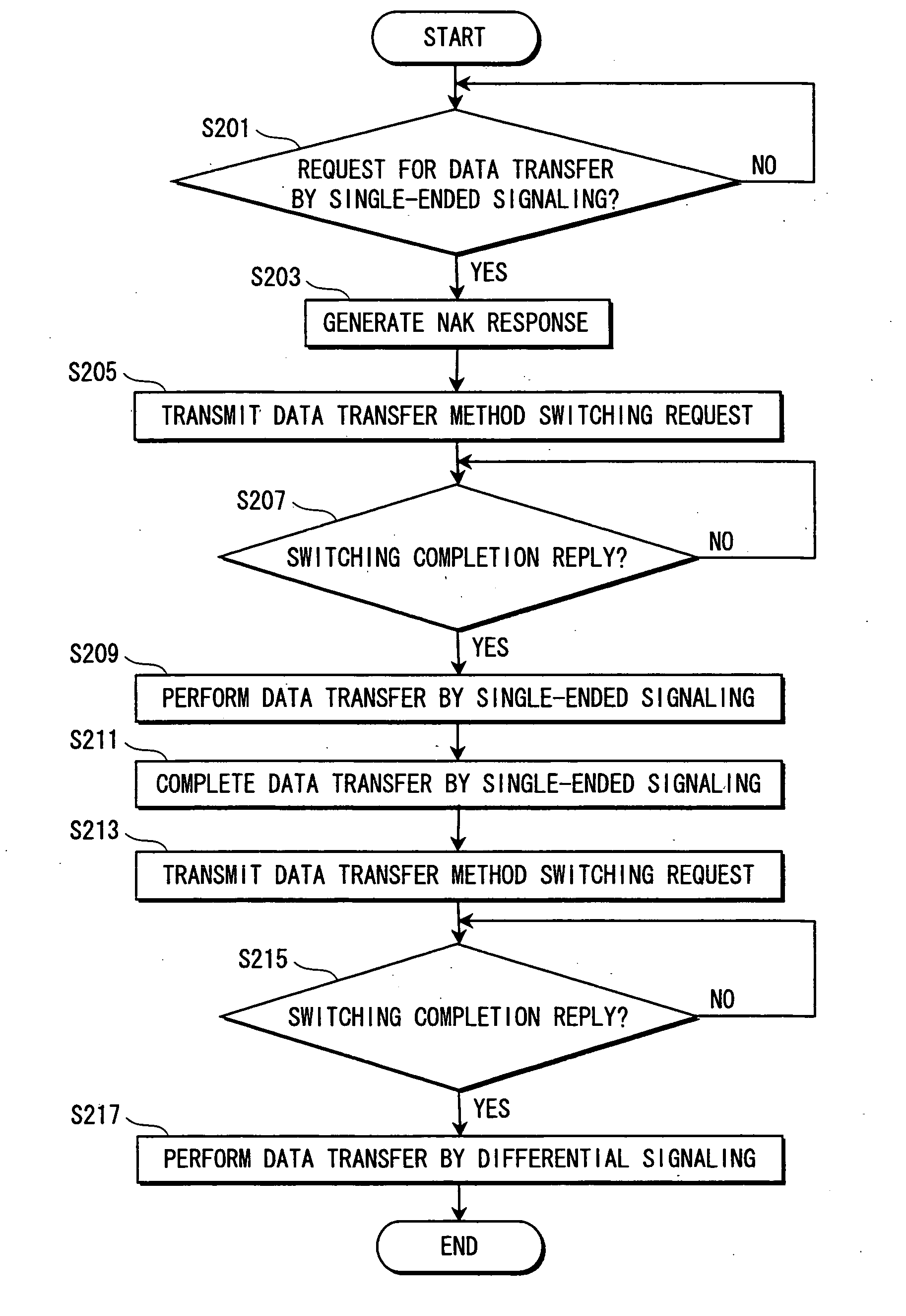
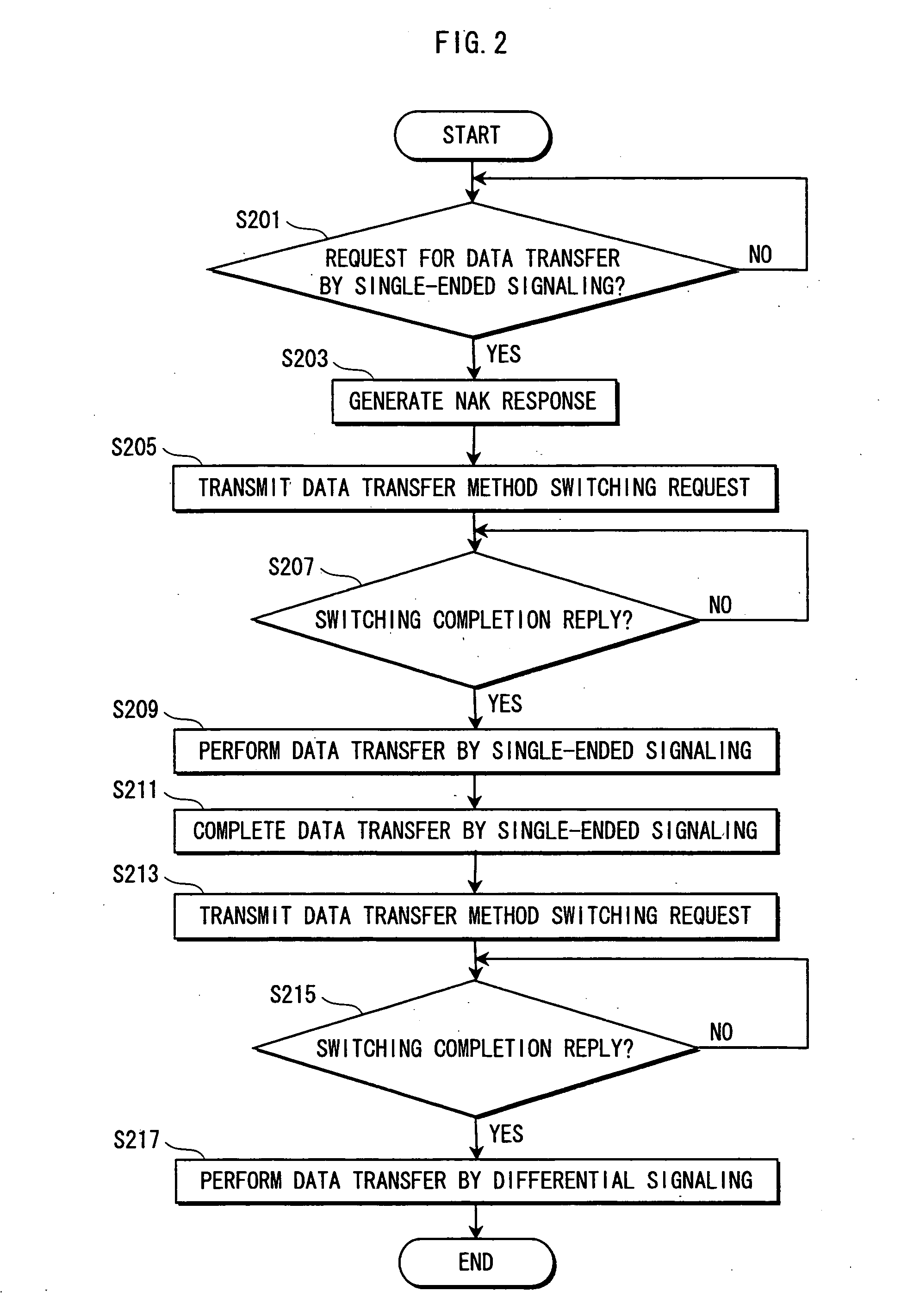
[0044] The following describes a communication apparatus according to a first embodiment of the present invention, with reference to drawings.
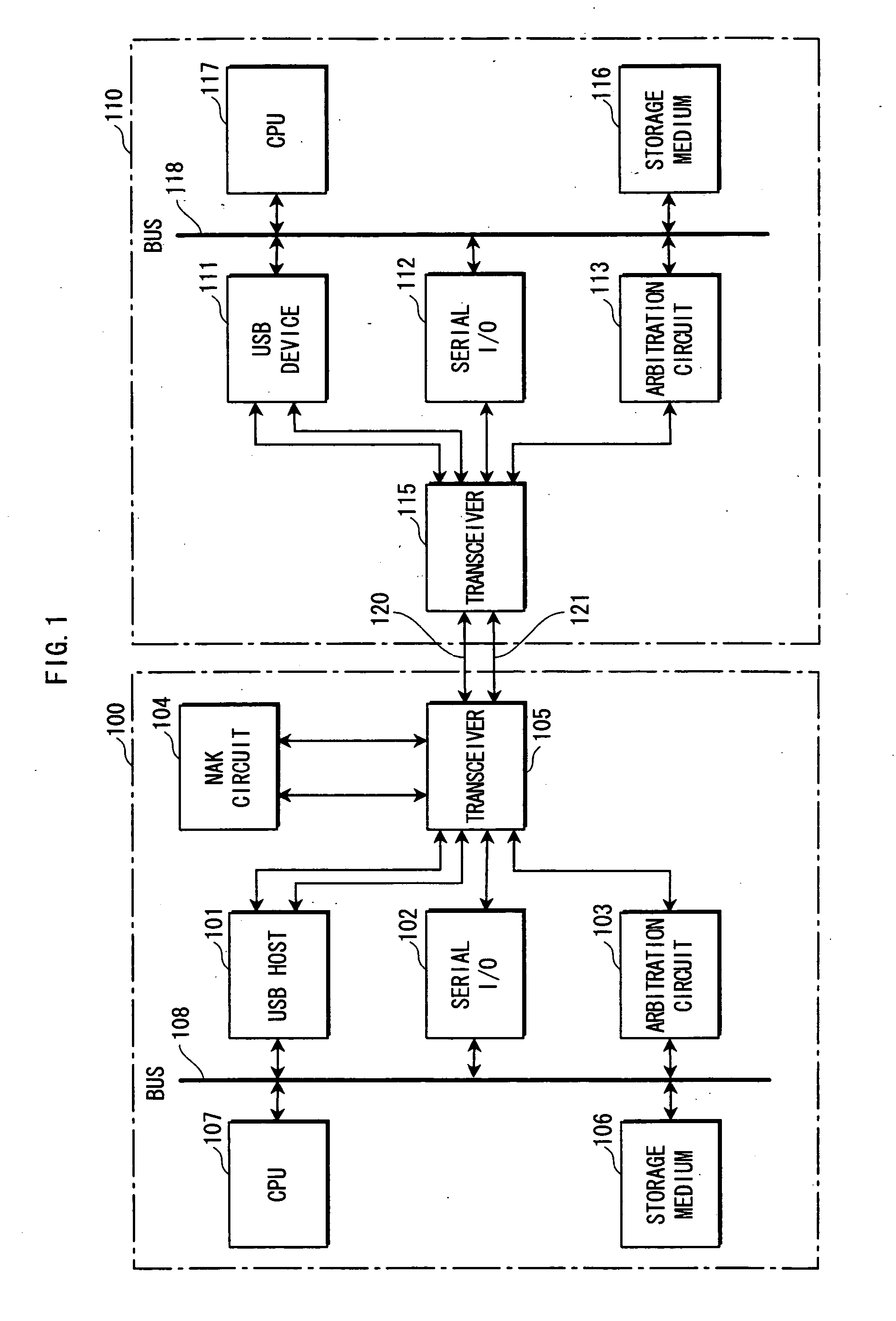
[0045]FIG. 1 shows an example system in which a communication apparatus 100 of the first embodiment is connected with another communication apparatus 110. The communication apparatus 100 serves as a host, and transfers data with the communication apparatus 110 connected to it. The host referred to here has functions of managing address assignment, data transfer timing, and the like with respect to the communication apparatus 110. Meanwhile, the communication apparatus 110 serves as a device.
[0046] The communication apparatus 100 includes a USB host 101, a serial I / O 102, an arbitration circuit 103, a NAK circuit 104, a transceiver 105, a storage medium 106, a CPU 107, and a bus 108. The communication apparatus 110 includes a USB device 111, a serial I / O 112, an arbitration circuit 113, a transceiver 115, a storage medium 116, a CPU 117, and ...
Example
Second Embodiment
[0074] A second embodiment of the present invention relates to another method of switching between differential signaling and single-ended signaling by a host and a device connected to the host.
[0075] The following describes a communication apparatus according to the second embodiment of the present invention, with reference to drawings.
[0076]FIG. 4 is a functional block diagram showing a construction of a communication apparatus 400 of the second embodiment.
[0077] In the drawing, the communication apparatus 400 includes a USB host 410, a serial I / O 420, an arbitration circuit 430, a NAK circuit 440, a transceiver 450, a storage medium 460, a CPU 470, and a bus 480. The communication apparatus 400 basically has a same construction as the communication apparatus 100 in the first embodiment. The difference from the first embodiment lies in that a synchronous port is newly included in the communication apparatus 400 to synchronize switching with a device connected ...
PUM
Abstract
To provide a communication apparatus which selectively performs a data transfer by differential signaling and a data transfer by single-ended signaling using a USB cable, where a USB host in the communication apparatus can recognize USB connection even when differential signaling is switched to single-ended signaling. The communication apparatus performs the data transfer by differential signaling using two data transfer signal lines in the USB cable, and the data transfer by single-ended signaling using one of the two data transfer signal lines. The communication apparatus includes a NAK circuit which, when differential signaling is switched to single-ended signaling, outputs a NAK response to the USB host to have the USB host recognize the USB connection.
Description
BACKGROUND OF THE INVENTION [0001] 1. Field of the Invention [0002] The present invention relates to a communication apparatus that performs data transfers using a USB (Universal Serial Bus) cable. [0003] 2. Related Art [0004] A data transfer using a USB cable is conducted in the following manner. When a device is connected to a host, the host detects the connection, and performs initialization such as assigning an address to the connected device, to enable a data transfer between the host and the device. After this, the data transfer is performed according to differential signaling. Differential signaling is a method of transferring data one bit at a time using two signal lines. In differential signaling, one signal line carries data of one phase, the other signal line carries data of an opposite phase, and the receiving end reads a difference in potential between the two signal lines as a signal value. Here, the difference takes one of two values. If the difference is large, the s...
Claims
Application Information
Patent Timeline
Application Date:The date an application was filed.
Publication Date:The date a patent or application was officially published.
First Publication Date:The earliest publication date of a patent with the same application number.
Issue Date:Publication date of the patent grant document.
PCT Entry Date:The Entry date of PCT National Phase.
Estimated Expiry Date:The statutory expiry date of a patent right according to the Patent Law, and it is the longest term of protection that the patent right can achieve without the termination of the patent right due to other reasons(Term extension factor has been taken into account ).
Invalid Date:Actual expiry date is based on effective date or publication date of legal transaction data of invalid patent.