
Image forming apparatus

Active Publication Date: 2013-02-21
CANON KK
View PDF0 Cites 17 Cited by
  • Summary
  • Abstract
  • Description
  • Claims
  • Application Information

AI Technical Summary

Benefits of technology

The present invention is designed to address three issues: reducing the space taken up by a printing machine, making it easier to feed paper, and making the access cover easier to use.

Problems solved by technology

However, in such a U-turn type paper feed and discharge system, if a discharged sheet comes into contact with a sheet on the paper feed tray, a paper feed resistance may be increased or fluctuated, thus causing an unfavorable paper feed such as a feed failure or a multi feed.
However, separate opening and closing operations of the three components including the paper feed tray, the paper discharge tray, and the access cover become troublesome, and if an order of the operations is set, this may increase a risk of an erroneous operation by a user.
Moreover, in order for the individual components to perform the opening and closing operations without causing an interference to one another, it is necessary to secure an enough space between the components, possibly causing an increase of the apparatus in size and an increase of the manufacturing cost.

Method used


Image

  • Image forming apparatus
  • Image forming apparatus
  • Image forming apparatus

Examples


Embodiment Construction

[0019]Exemplary embodiments of the present invention are described below with reference to the accompanying drawings.

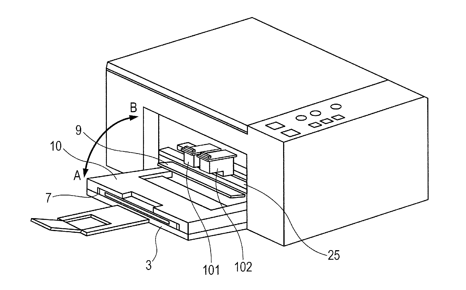
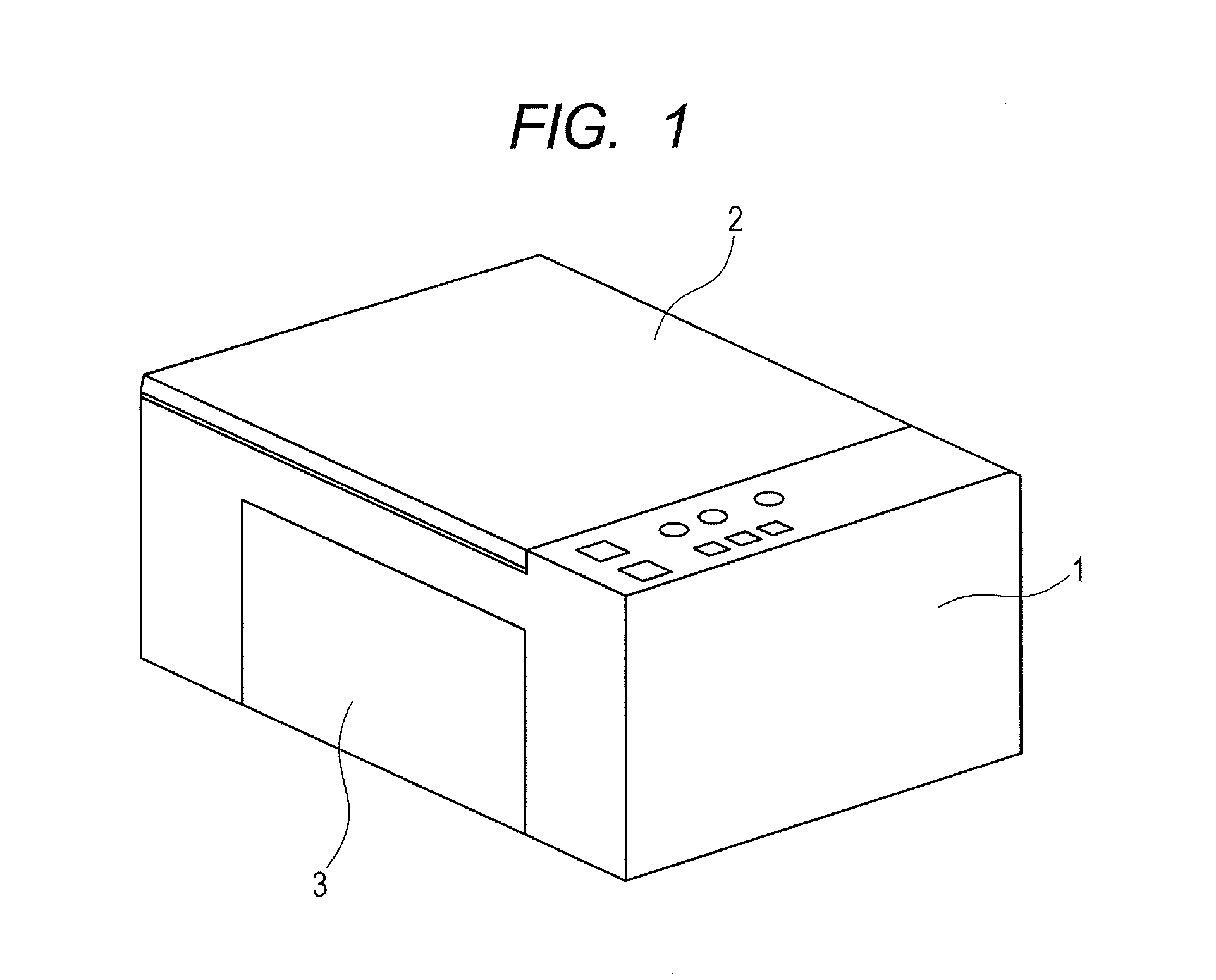
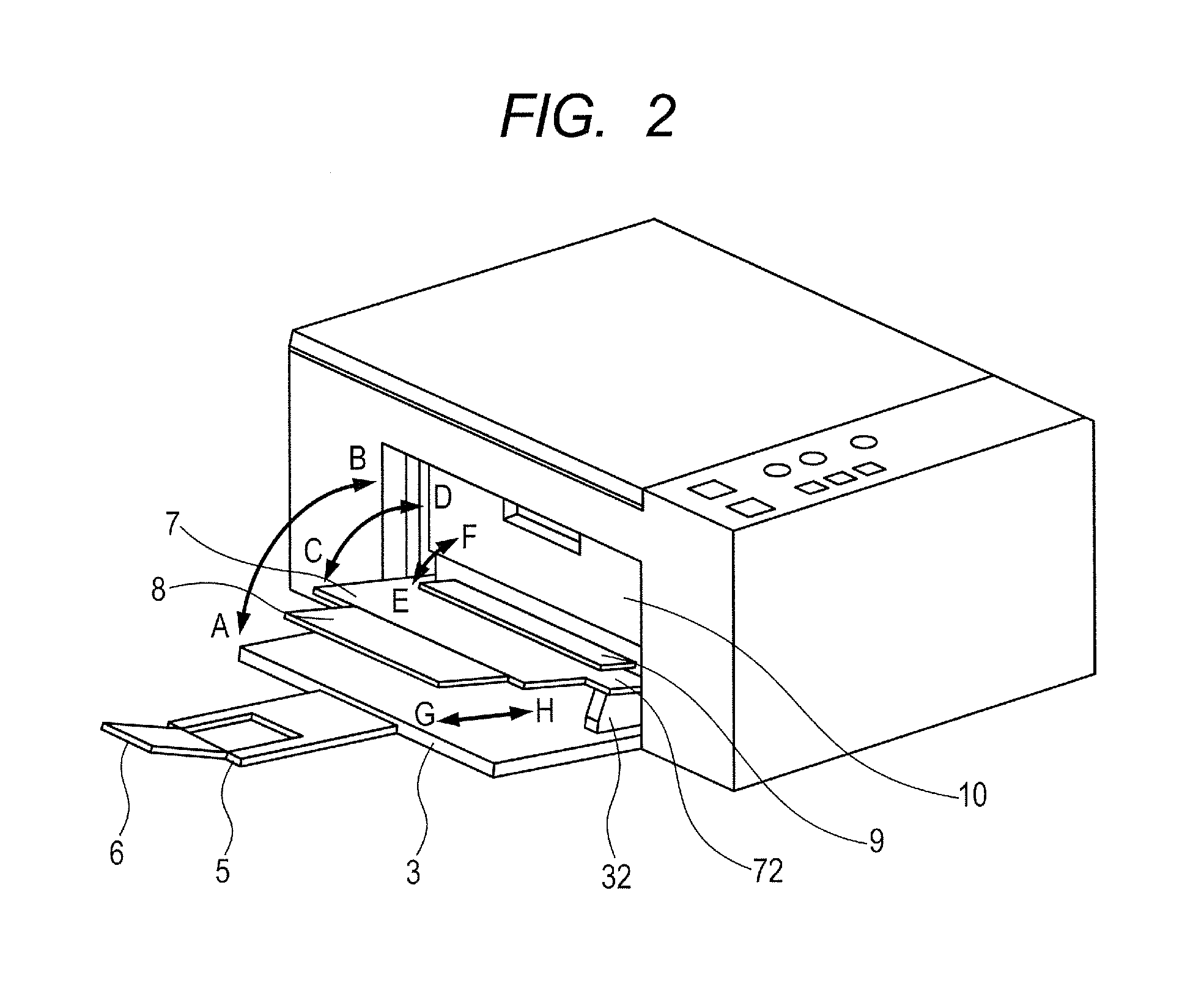
[0020]FIG. 1 is a perspective view of an image forming apparatus, for illustrating an accommodated state according to an embodiment of the present invention, and FIG. 4 is a cross-sectional view for illustrating the accommodated state. FIG. 2 is a perspective view of the image forming apparatus, for illustrating an image forming state according to the embodiment of the present invention, and FIG. 5 is a cross-sectional view for illustrating the image forming state. FIG. 3 is a perspective view of the image forming apparatus, for illustrating a maintenance state according to the embodiment of the present invention, and FIG. 6 is a cross-sectional view for illustrating the maintenance state.

[0021]FIGS. 1 and 4 illustrate an image forming apparatus including an image reading apparatus in which an original cover 2 that is opened and closed when placing an original and a p...


PUM

PropertyMeasurementUnit
Lengthaaaaaaaaaa

Abstract

An image forming apparatus includes a housing having an access cover, a paper feed tray, and a paper discharge tray provided on a side thereof in a rotatable manner. A rotation pivot of the paper feed tray and a rotation pivot of the access cover are arranged on the same axis, and a rotation pivot of the paper discharge tray is arranged with a shift from the rotation pivot of the access cover.

Description

BACKGROUND OF THE INVENTION[0001]1. Field of the Invention[0002]The present invention relates to an image forming apparatus, and more particularly, to a configuration of a discharge sheet tray for supporting a printed sheet, which is capable of maintaining positional relationships with a feed sheet tray, on which a sheet to be fed to a printing portion in the apparatus is placed, and with an access door for replacing an ink tank.[0003]Although a case in which a sheet to be printed is a paper sheet is described in the specification, the sheet may be any printable sheet recording medium other than the paper sheet. In addition, when a description is given below by taking the paper sheet as an example, the feed sheet tray may be referred to as a paper feed tray and the discharge sheet tray may be referred to as a paper discharge tray.[0004]2. Description of the Related Art[0005]As an image forming apparatus such as a color printer, there is an image forming apparatus including, on a fro...

Claims


Application Information

Patent Timeline
IPC IPC(8): B41J29/13
CPCB41J29/13B65H1/28B65H31/02B65H31/20B65H2301/3122B65H2301/4212B65H2402/441B65H2402/46B65H2404/743B65H2405/11164B65H2405/1117B65H2405/3322B65H2601/321B65H2701/1311B65H1/04B65H2405/324B65H29/52
Inventor TAKEMURA, MAKOTOSHIMMACHI, MASAYATSUBAKIMOTO, YASUHITOTOKUYAMA, KANETO
Owner CANON KK
Learn More