Base station and communication method

Inactive Publication Date: 2011-04-14
SOVEREIGN PEAK VENTURES LLC
View PDF7 Cites 18 Cited by
  • Summary
  • Abstract
  • Description
  • Claims
  • Application Information

AI Technical Summary

Benefits of technology

[0035]According to the present invention, even when a large number of terminals pass through the communication area in a short tim

Problems solved by technology

However, the wireless terminal is compact, and extremely low in power consump

Method used


Image

  • Base station and communication method
  • Base station and communication method
  • Base station and communication method

Examples


Example

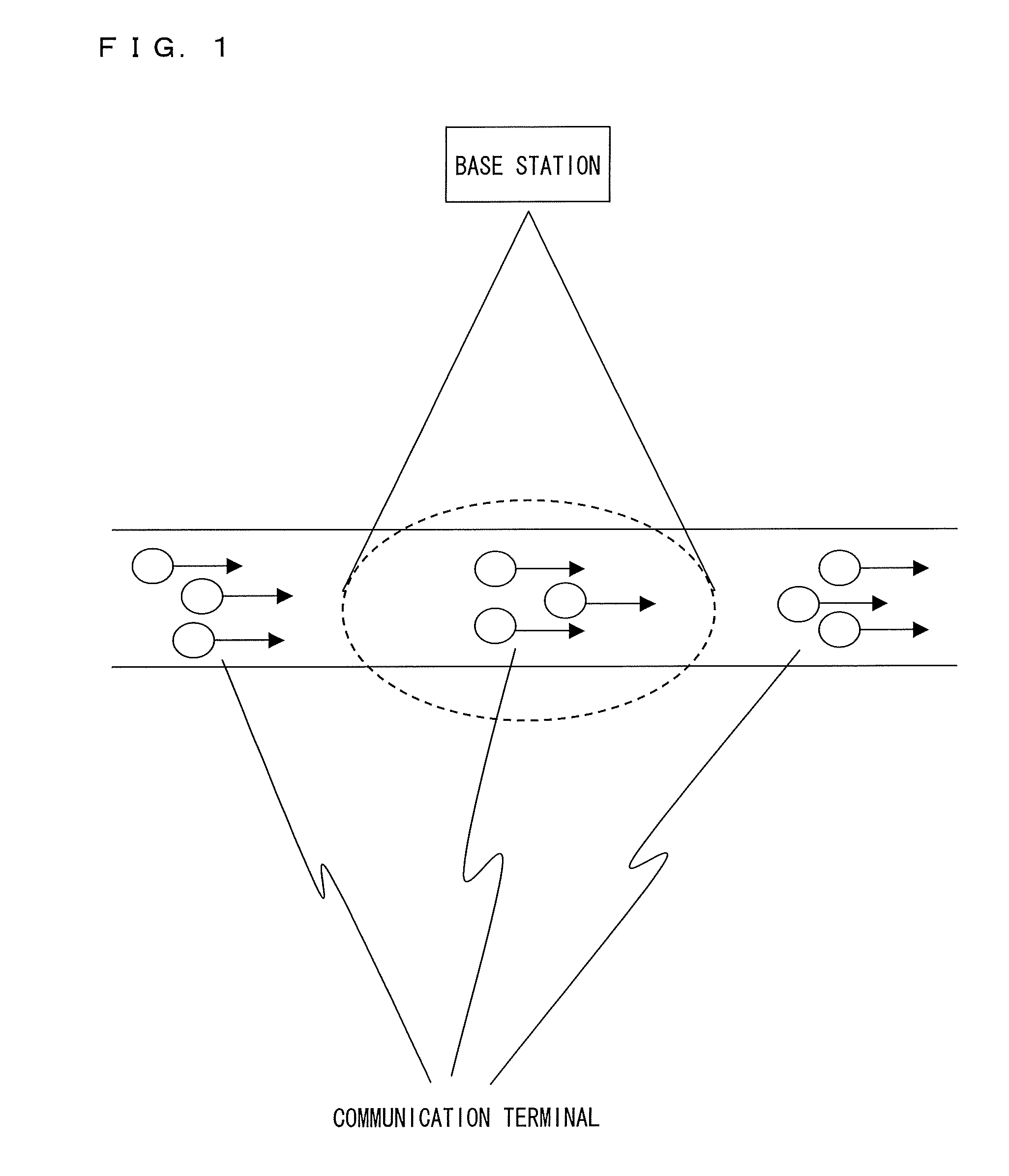
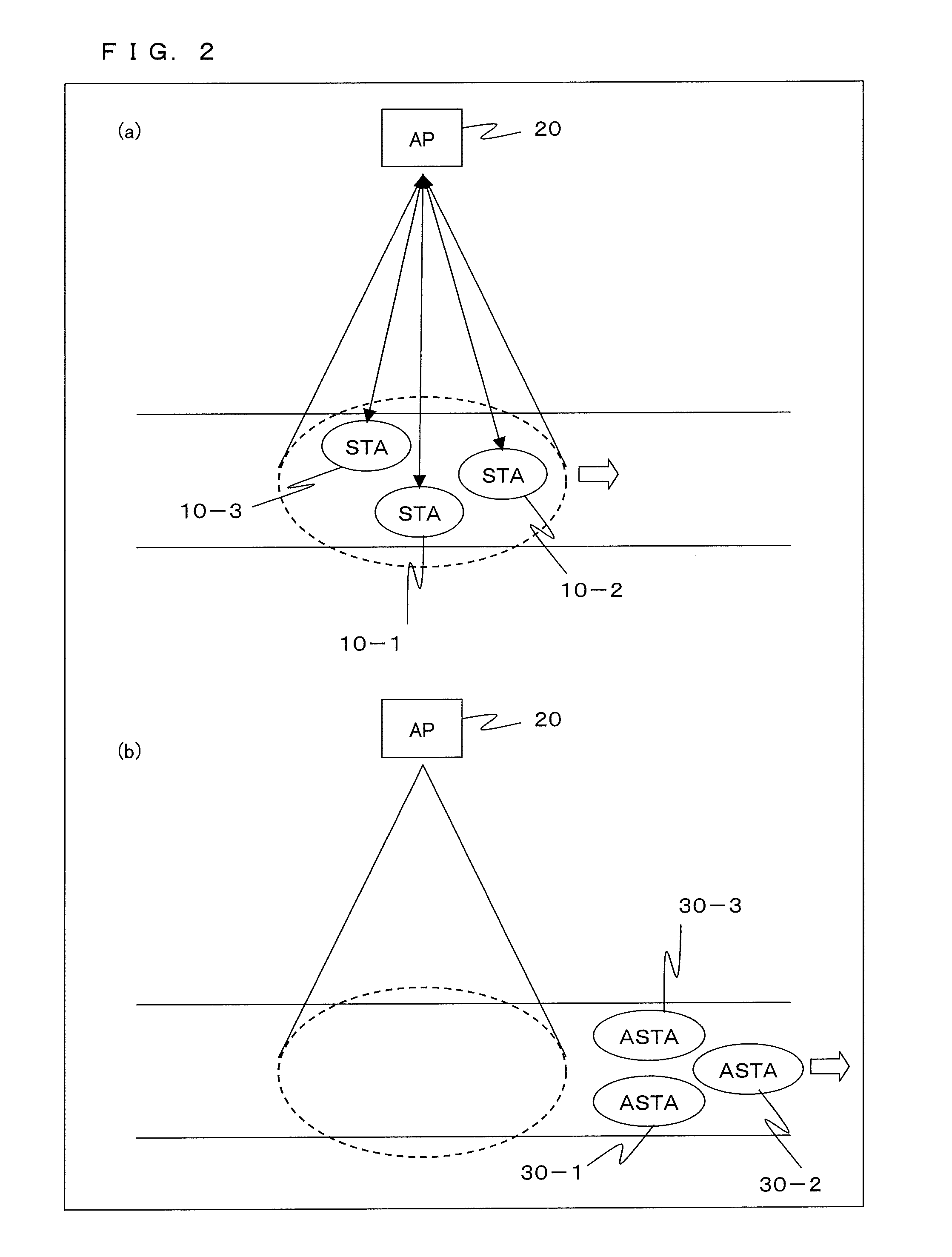
[0053]Hereinafter, a first embodiment of the present invention will be described. FIG. 2 is a network diagram illustrating a network including a base station and communication terminals according to this embodiment. FIG. 2 shows an example of a network configuration utilizing multi-channels. With reference to (a) of FIG. 2, in a communication area of a control terminal AP 20 as a base station, communication terminals STA10-1, 10-2, and 10-3 use different channels CH1 to CH3, respectively, and the AP 20 receives data transmitted from the terminals STA10-1 to 10-3 to perform authentication. With reference to (b) of FIG. 2, the terminals STA10-1 to 10-3 that have performed authentication with the AP 20 become authenticated communication terminals ASTA30-1 to 30-3, respectively, and go out of the communication area of the AP 20.

[0054]FIG. 3 is a functional block diagram illustrating a communication terminal STA10 used in this embodiment. The terminal STA10 includes an antenna 101, a wir...

Example

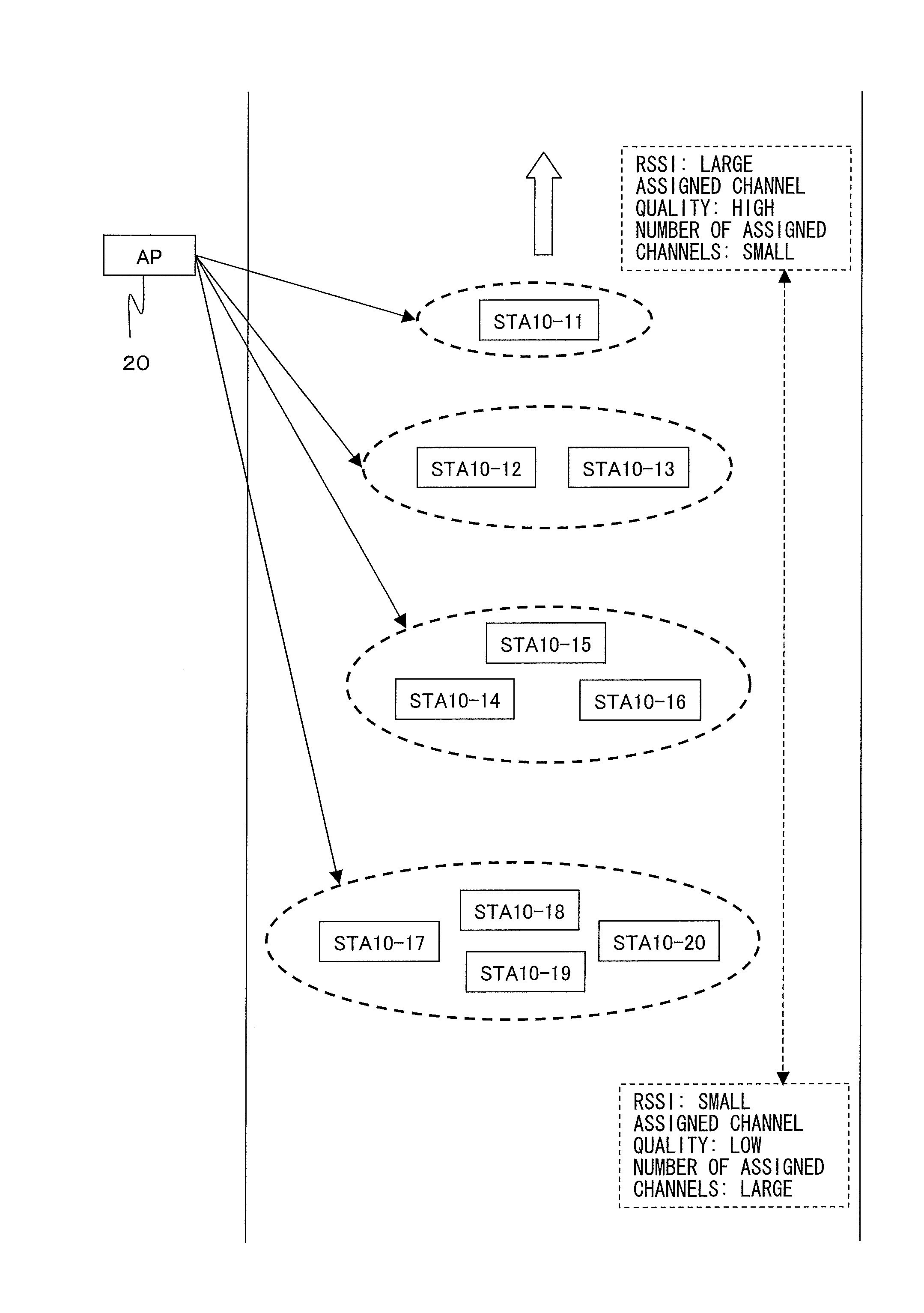
[0119]Hereinafter, a second embodiment of the present invention will be described. In the first embodiment, a channel having a higher quality is assigned to a terminal STA having a larger RSSI value. This second embodiment is different from the first embodiment in that, when a terminal STA10 the latest RSSI value of which is lower than the previously-measured RSSI value is detected, exceptionally a channel of a highest quality is preferentially assigned to this terminal STA10 over a terminal STA10 having a largest RSSI value. This difference will be described hereinafter.

[0120]The RSSI table of the first embodiment shown in FIG. 9 is merely overwritten with updated RSSI values every time RSSI measurement is conducted. On the other hand, in the RSSI table of this second embodiment, as shown in FIG. 15, the RSSI values are updated, and moreover, when an updated value is smaller than the previously measured value, a flag indicating this is stored.

[0121]In the example shown in FIG. 15, ...


PUM


Abstract

A base station includes: an estimation section estimating transmission condition of each of frequency channels used for communication; a reception section receiving a data signal from each communication terminal through any of the frequency channels; a measurement section measuring received signal power of the received data signal for each frequency channel; a determination section determining, for each frequency channel, whether the received data signal is demodulated errorlessly; and a control section assigning frequency channels estimated as being in good transmission condition by the estimation section, to communication terminals the data signals of which are determined as not being errorlessly demodulated by the determination section, such that a frequency channel in a better transmission condition is assigned preferentially to a communication terminal having larger received signal power detected by the detection section, and transmitting retransmission request signals requesting the communication terminals to retransmit the data signals using the assigned frequency channels.

Description

TECHNICAL FIELD[0001]The present invention relates to a wireless communication system having a large number of terminals, and more particularly, to a method of selecting channels and times in wireless networks such as a sensor network and an active RF tag system, which include a large number of terminals.BACKGROUND ART[0002]In recent years, networks such as a WPAN (Wireless Personal Area Network) and a sensor network, which include compact and low-power-consumption wireless terminals, are attracting attention. As a system similar to these networks, there is a system using active RF tags, each tag actively emitting a wireless signal. A wireless terminal used in these networks has a low data rate (from several kbps to several hundreds of kbps), and a short wireless-signal reaching distance (from several meters to several tens of meters). However, the wireless terminal is compact, and extremely low in power consumption so that it is drivable for several years with a battery embedded th...

Claims


Application Information

Patent Timeline
IPC IPC(8): H04W72/08
CPCH04L1/1893H04W72/085H04W28/04H04L5/06H04W72/542
Inventor YAMAMOTO, NAOTAKEHAYASHINO, HIROSHINAKAE, HIRONORISHIRAKATA, NAGANORI
Owner SOVEREIGN PEAK VENTURES LLC
Why Eureka
Try Eureka