Battery pack for electric car

Active Publication Date: 2014-10-30
HONDA MOTOR CO LTD
View PDF1 Cites 18 Cited by
  • Summary
  • Abstract
  • Description
  • Claims
  • Application Information

AI Technical Summary

Benefits of technology

[0011]In accordance with the first aspect of the present invention, since the main switch is disposed above the first battery module group on one side of the vehicle body frame, which extends in the vehicle width direction, and the junction board is disposed above the second battery module group on the other side of the vehicle body frame, it is possible to maximize vehicle compartment space by dividing the main switch and the junction board between the front and the rear of the vehicle body frame. Furthermore, when the plurality of second high voltage cables connecting the plurality of battery module rows of the first battery module group to the corresponding plurality of battery module rows of the second battery module group are bent into a U-shape and passed through beneath the vehicle body frame, since the bent parts of the second high voltage cables are held by the cable holder and fixed to the fixing part, it is possible to stop by means of the cable holder the second high voltage cable from extending linearly by virtue of its self stiffness, thus not only making a wiring operation of the second high voltage cable easy but also preventing a large load from being imposed on a part connecting the second high voltage cable to the battery module. Moreover, since only the bus bar disposed in the intermediate part of the first high voltage cable is bent into a U-shape and passed through beneath the vehicle body frame, not only is a wiring operation of the first high voltage cable easy, but it is also possible to minimize the length of the bus bar to thus enhance the reliability with respect to vibration.
[0012]Furthermore, in accordance with the second aspect of the present invention, the first high voltage cable extending from the junction board passes through the first battery module group and is connected to the output part, and in this arrangement since the bus bar d

Problems solved by technology

A plurality of batteries of a battery pack for an electric car are connected to each other via a cable or a bus bar and are also connected to a main switch or a junction board, but unless the cable, the bus bar, the main switch, the junction

Method used


Image

  • Battery pack for electric car
  • Battery pack for electric car
  • Battery pack for electric car

Examples


Example

First Embodiment

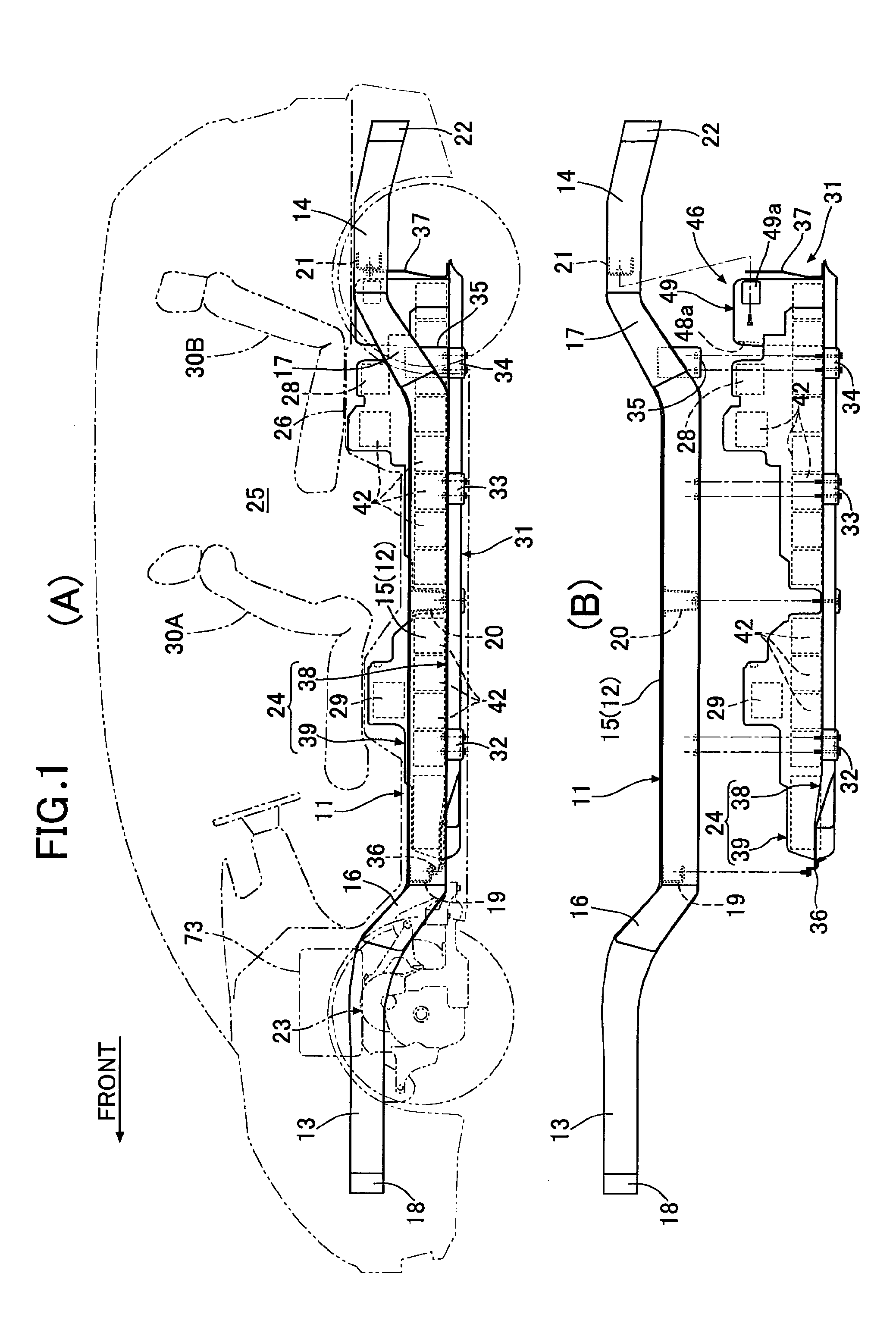
[0039]As shown in FIG. 1, a vehicle body frame 11 of an electric automobile includes a pair of left and right floor frames 12 and 12 extending in the vehicle body fore-and-aft direction, a pair of left and right front side frames 13 and 13 extending forwardly from the front ends of the floor frames 12 and 12 while bending upwardly, a pair of left and right rear side frames 14 and 14 extending rearwardly from the rear ends of the floor frames 12 and 12 while bending upwardly, a pair of left and right side sills 15 and 15 disposed outside, in the vehicle width direction, of the floor frames 12 and 12, a pair of left and right front outriggers 16 and 16 connecting the front ends of the side sills 15 and 15 to the front ends of the floor frames 12 and 12, a pair of left and right rear outriggers 17 and 17 connecting the rear ends of the side sills 15 and 15 to the rear ends of the floor frames 12 and 12, a front bumper beam 18 providing a connection between front end pa...


PUM


Abstract

In a battery pack for an electric car, a plurality of battery modules are mounted to be divided between the front and rear of a middle cross member and a main switch and a junction board are disposed in the front and rear of the middle cross member respectively. A bent part of a second high voltage cable, which bends into a U-shape and pass through beneath the middle cross member, is held by a cable holder and fixed to a fixing part. Since only a bus bar disposed in the intermediate part of the first high voltage cable is bent into a U-shape and passed through beneath the middle cross member, not only is a wiring operation of the first high voltage cable easy, but it is also possible to minimize the length of the bus bar to thus enhance the reliability with respect to vibration.

Description

TECHNICAL FIELD[0001]The present invention relates to a battery pack for an electric car, the battery pack including a plurality of battery module rows each having a plurality of battery modules disposed in a row extending in the fore-and-aft direction so as to straddle a vehicle body frame extending in a vehicle width direction, the plurality of battery modules being electrically connected in series, the battery modules, of the plurality of battery module rows, that are positioned on one side of the vehicle body frame forming a first battery module group, and the battery modules, of the plurality of battery module rows, that are positioned on the other side of the vehicle body frame forming a second battery module group.BACKGROUND ART[0002]A battery pack for an electric car in which a plurality of battery housing parts are defined by disposing a lattice-shaped partition frame on an upper face of a plate-shaped battery frame for the electric car, and a plurality of batteries are mou...

Claims


Application Information

Patent Timeline
IPC IPC(8): H01M2/10H01M10/42H01M50/204H01M50/249H01M50/298H01M50/503H01M50/509H01M50/528H01M50/574
CPCH01M2/1083H01M10/425H01M2010/4271H01M2/34H01M2220/20Y02T10/7061B60L11/1805B60R16/04B60L11/1864B60L11/1879H01M2/206B60L2240/545B60L2270/147Y02T10/7005Y02T10/705B60L11/1877B60L2240/36B60L2270/145B60L11/1874B60L1/003B60L50/64B60L50/66B60L58/21B60L50/52B60L58/26H01M50/574H01M50/509H01M50/503H01M50/298H01M50/249H01M50/204Y02T10/70Y02E60/10
Inventor SAKAI, HIDEAKITACHIKAWA, KOSUKEKAWAHARA, MAKOTO
Owner HONDA MOTOR CO LTD
Why Eureka
Try Eureka