Thermosensitive flow rate detecting element and method for the manufacture thereof

Inactive Publication Date: 2005-01-25
MITSUBISHI ELECTRIC CORP
View PDF5 Cites 6 Cited by
  • Summary
  • Abstract
  • Description
  • Claims
  • Application Information

AI Technical Summary

Benefits of technology

Therefore, the present invention is able to provide a method for manufacturing a thermosensitive flow rate detecting element enabling irregularities in the

Problems solved by technology

Thus, irregularities in the size of the diaphragm portion lead to irregularities in the amount of heat transferred through the diaphragm portion to the frame 66.
As a result, one problem has been that flow rate detection characteristics differ among first thermosensitive flow rate detecting elements 60, preventing accurate flow rate detection.
Thus, one problem has been that irregularities arise in medium temperature detection performance as a result of the irregularities in the size of the diaphragm portion.
Furthermore, when a backfire occurs, a pressure of nearly two atmospheres may also act on the thermosensitive flow rate detecting element.
Thus, when a thermosensitive flow rate detecting element having a diaphragm construction is subjected to mechanical stress of this kind, if the size of the diaphragm portion is larger than a design value (a desired value), or if there is an abnormality in the shape of the diaphragm portion, problems arise such as the diaphragm portion being damaged.
As a result, in the first thermosensitive flow rate detecting element 60, irregularities arise in the flow rate

Method used


Image

  • Thermosensitive flow rate detecting element and method for the manufacture thereof
  • Thermosensitive flow rate detecting element and method for the manufacture thereof
  • Thermosensitive flow rate detecting element and method for the manufacture thereof

Examples


Example

Embodiment 1

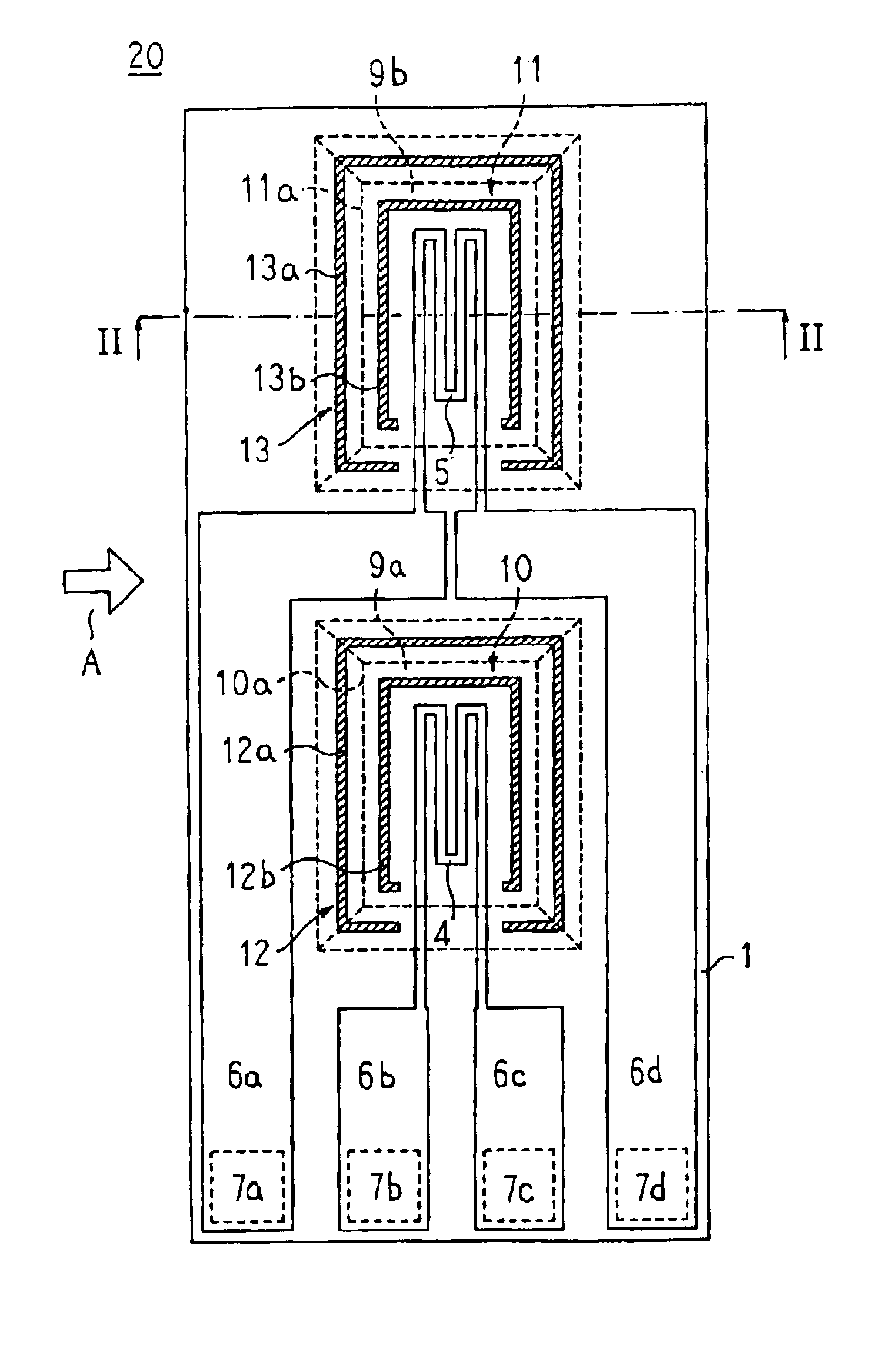
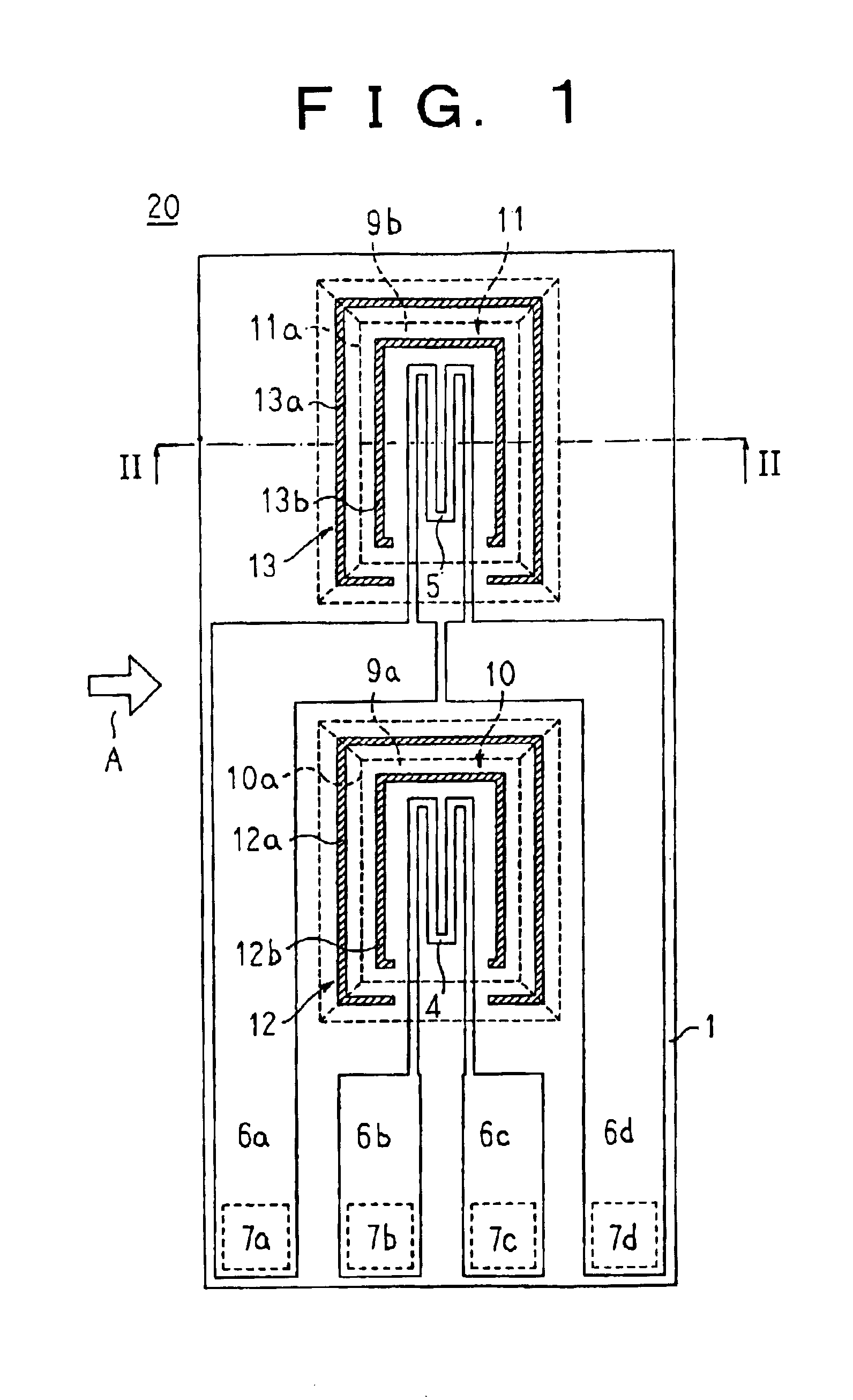
FIG. 1 is a front elevation showing a thermosensitive flow rate detecting element according to Embodiment 1 of the present invention, and FIG. 2 is a cross section taken along line II—II in FIG. 1 viewed from the direction of the arrows. Here in FIG. 1, a direction of flow of a fluid being measured relative to the flow rate detecting element is indicated by an arrow A, and in order to make the construction easier to see, a protective layer has been removed. Furthermore, in order to make the construction easier to see, FIGS. 1 and 2 are not drawn to actual scale. Moreover, the same applies to each of the figures below.

In FIGS. 1 and 2, an electrically-insulating support film 2 is formed over an entire front surface 1a of a flat substrate 1 made by silicon, a resistance heater 4 functioning as a resistor made by a thermosensitive resistor film, a fluid temperature resistance thermometer 5 functioning as a resistor, first to fourth lead patterns 6a to 6d, a resistance heate...

Example

Embodiment 2

FIG. 12 is a front elevation showing a thermosensitive flow rate detecting element according to Embodiment 2 of the present invention.

In a thermosensitive flow rate detecting element 20A according to Embodiment 2, as indicated by hatching in FIG. 12, first patterns 16a and 17a formed outside four edge portions 10a and 11a of the first and second diaphragm portions 10 and 11 so as to lie alongside the edge portions 10a and 11a are formed on the patterns of first to fourth lead patterns 15a to 15d. Second patterns 16b and 17b are formed inside four edge portions 10a and 11a of the first and second diaphragm portions 10 and 11 so as to lie alongside the edge portions 10a and 11a. A resistance heater dummy pattern 16 is constituted by the first pattern 16a and the second pattern 16b, and a resistance thermometer dummy pattern 17 is constituted by the first pattern 17a and the second pattern 17b.

Here, the first and second patterns 16a, 16b, 17a, and 17b are formed to dimensi...

Example

Embodiment 3

FIG. 13 is a diagram explaining a shape inspection process for the diaphragm portion of the thermosensitive flow rate detecting element according to Embodiment 3 of the present invention.

In FIG. 13, a diaphragm portion shape inspection apparatus 50 is constituted by: a stage 52 for fixing and moving a silicon wafer 51 on which thermosensitive flow rate detecting elements 20 have been prepared; a camera 53 functioning as an imaging device for taking images of a front surface of the thermosensitive flow rate detecting elements 20; an image processing device 54 for processing the images taken by the camera 53, recognizing the resistance heater and resistance thermometer dummy patterns 12 and 13 and the edge portions 10a and 11a of the first and second diaphragm portions 10 and 11, and determining whether the first and second diaphragm portions 10 and 11 are normal or abnormal from the positional relationship between the dummy patterns 12 and 13 and the edge portions 10a and...


PUM


Abstract

A dummy pattern is constituted by frame-shaped first patterns formed on a flat substrate so as to surround a resistance heater and a fluid temperature resistance thermometer, and frame-shaped second patterns formed on inner perimeter sides of the first patterns, edge portions of first and second diaphragm portions being positioned between the first patterns and the second patterns.

Description

BACKGROUND OF THE INVENTION1. Field of the InventionThe present invention relates to a flow rate sensor for measuring an amount of intake air in an internal combustion engine, for example, and relates particularly to a thermosensitive flow rate detecting element provided with a heating element for measuring a flow velocity or flow rate of a fluid based on heat transfer to the fluid from the heating element or a portion heated by the heating element, and further relates to a method for the manufacture thereof.2. Description of the Related ArtFIG. 14 is a front elevation showing a first conventional thermosensitive flow rate detecting element such as described in Japanese Patent Laid-Open No. HEI 6-249693, for example, and FIG. 15 is a cross section taken along line XV—XV in FIG. 14 viewed from the direction of the arrows.In FIGS. 14 and 15, first and second films 63 and 64 are formed separately on a front surface of a silicon substrate 67 made by a single-crystal silicon. A measuring...

Claims


Application Information

Patent Timeline
IPC IPC(8): G01F1/684G01F1/68F02D35/00G01F1/692H01L37/00
CPCG01F1/6845G01F1/68
Inventor KAWAI, MASAHIROTAGUCHI, MOTOHISA
Owner MITSUBISHI ELECTRIC CORP
Why Eureka
Try Eureka