Damping element

a technology of pedicle screws and elements, applied in the field of pedicle screws, can solve the problem of predetermined distance between the pedicle screws

Inactive Publication Date: 2006-12-28
SYNTHES USA
View PDF14 Cites 152 Cited by
  • Summary
  • Abstract
  • Description
  • Claims
  • Application Information

AI Technical Summary

Benefits of technology

[0004] The object of the invention is to produce a damping element that can polyaxially pivot about at least one of its ends and is axially, telescopingly connected to a longitudinal support.

Problems solved by technology

A disadvantage of this known damping element is that due to the geometry of the damping element, the distance between the pedicle screws is predetermined.

Method used


Image

  • Damping element
  • Damping element
  • Damping element

Examples


Embodiment Construction

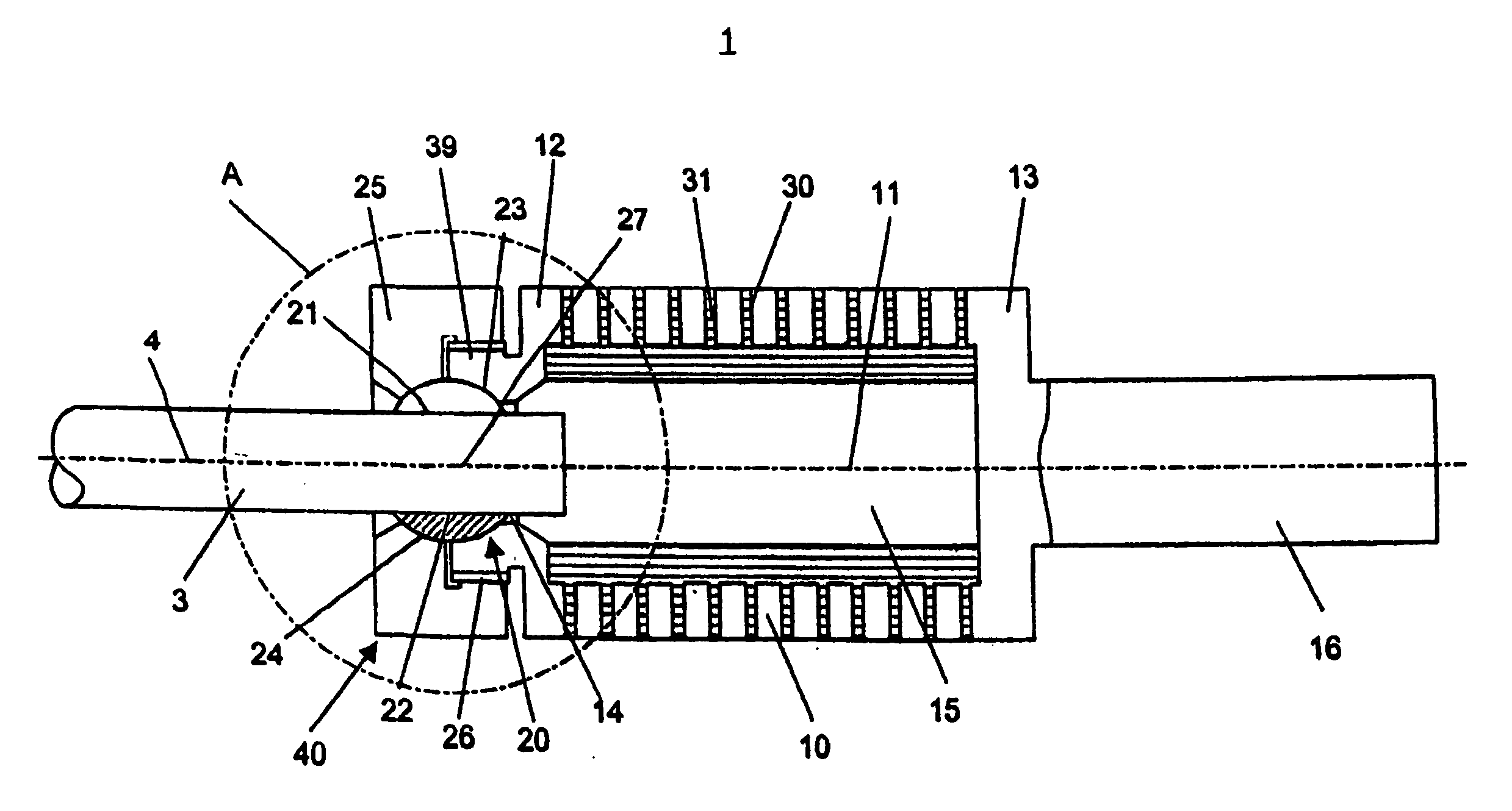
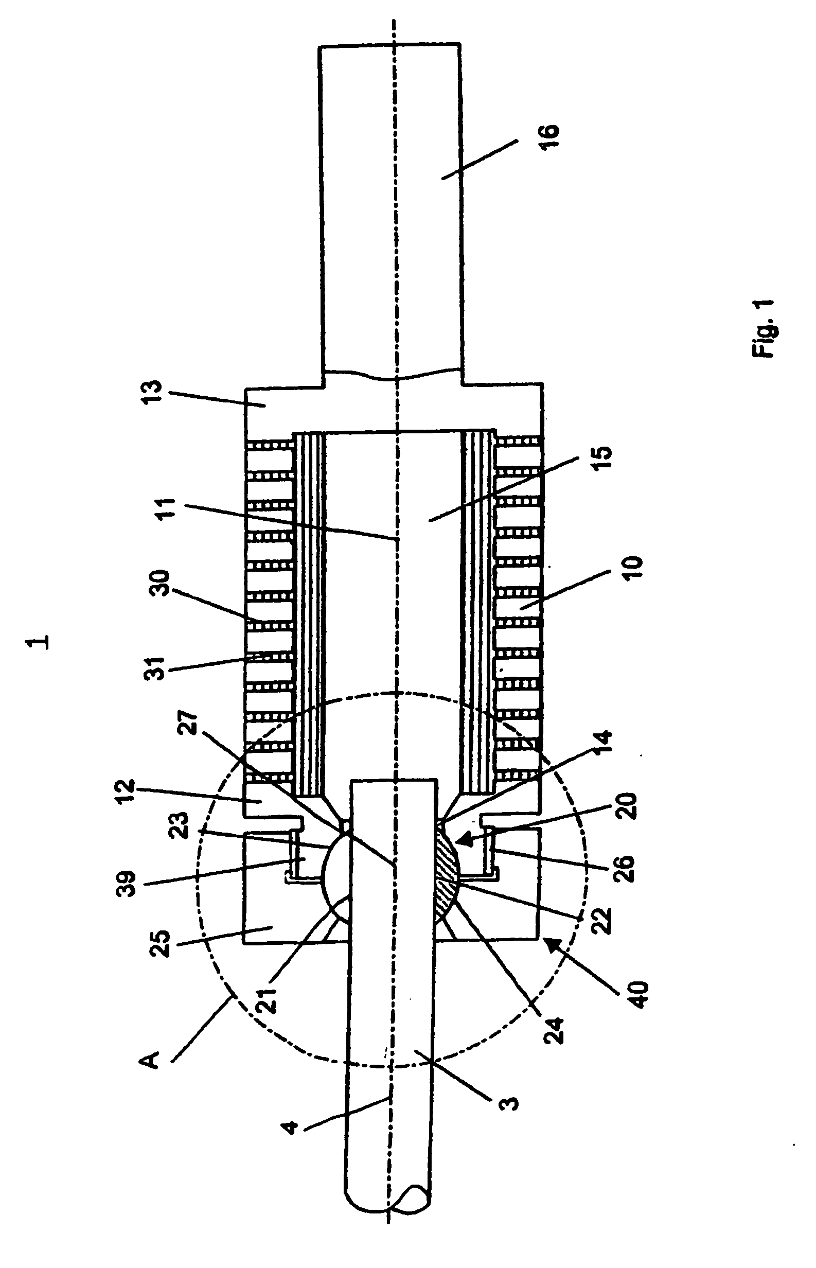
[0020]FIGS. 1 and 2 illustrate an embodiment that comprises a hollow cylindrical damping element 1 with a central axis 11 and a releasably lockable ball joint 20 for a polyaxial connection of the damping element 1 with a rod-shaped longitudinal support 3 having a longitudinal axis 4. In addition to the ball joint 20, the damping element 1 includes a spring element 10 that in the embodiment illustrated is made from a metal helical spring and a plastic part 31 which penetrates into a gap 30 between the coils of the spring and reduces the diameter of the hollow space 15. The ball joint 20 is provided on the first end 12 of the spring element 10, whereas on the second, axially opposed end 13 of the spring element 10, a coaxial rod-shaped connecting part 16 is provided. Connecting part 16 is suitable to be connected to a further part (not illustrated) of a vertebra-stabilizing device.

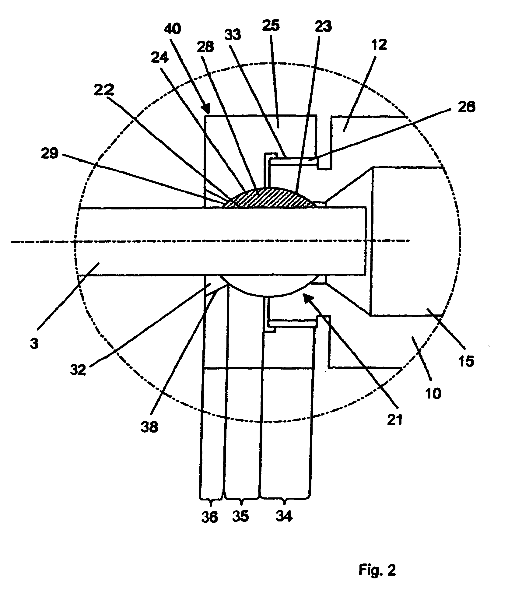
[0021] The ball joint 20 comprises in this case a spherically convex clamping body 21 with a central bor...


PUM


Abstract

A damping element for the dynamic stabilization of two bones, particularly of two adjacent bodies of the vertebra, has a central axis, a first end intersecting the central axis, a second end intersecting the central axis, and a spring element between the two ends and coaxial with the central axis. The damping element also has a ball-joint connection at at least one end that is concentric with the central axis. The ball-joint connection operative to receive and releasably lock a rod-shaped longitudinal support therein.

Description

CROSS REFERENCE TO RELATED APPLICATION [0001] This is a continuation of International Patent Application No. PCT / CH2003 / 00648, filed Sep. 29, 2003, the entire contents of which are incorporated herein by reference thereto.TECHNICAL FIELD OF THE INVENTION [0002] The invention is directed to a damping element having a spring element and at least one ball-joint connection for receiving a rod-shaped longitudinal support. BACKGROUND OF THE INVENTION [0003] Damping elements for the dynamic stabilization of two adjacent bodies of the vertebra are known. For example, one known damping element comprises a coaxial damping body with a spherically convex axially protruding connecting part at each axial end that can be secured to two respective pedicle screws. By virtue of the spherical joint between the two connecting parts and the heads of the pedicle screws, the damping element can be connected to the pedicle screws with varying angles between the longitudinal axes of the pedicle screws and t...

Claims


Application Information

Patent Timeline
Patent Type & Authority Applications(United States)
IPC IPC(8): A61B17/56A61B17/70
CPCA61B17/7013A61B17/7028A61B17/7023
Inventor HARTMANN, STEPHAN
Owner SYNTHES USA
Why Eureka
Try Eureka