Sleeping device and sleeper 's in-bed state detection method

a technology of in-bed state and sleeper, which is applied in the field of bed and in-bed state detection method, can solve the problems of degrading the comfortability of the bed, increasing the cost of the bed, and increasing the sensitivity of the sensor itsel

Inactive Publication Date: 2007-01-11
PANASONIC CORP
View PDF0 Cites 48 Cited by
  • Summary
  • Abstract
  • Description
  • Claims
  • Application Information

AI Technical Summary

Benefits of technology

[0068] According to this bed, the heartbeat vibration can be surely detected and a care bed being comfortable to sleep can be obtained.

Problems solved by technology

However, like the first example, in the bed in which the sensors formed by the many piezoelectric elements are provided on the upper surface of the bed on which the bedded person lies, many expensive sensors are disposed in a lattice pattern, so that the cost of the bed is inevitably raised.
Further, since the sensitivity of the sensor itself is relatively low, the sensors are required to be provided almost just on the upper surface of the bed on which the bedded person lies, whereby the comfortability of the bed is degraded.
Further, like the second example, also in the bed in which the piezoelectric sensors each having the long tape shape are disposed in the width direction, it is possible to detect whether a person is in bed or not, but it is impossible to monitor the positional shift of the person on the bed to prevent the person from falling etc. in advance.
Further, also in the case of this bed, since the piezoelectric sensors are provided on the upper surface of the bed on which the bedded person lies, it is inevitable to degrade the comfortability of the bed.
However, the conventional electrically operated bed of this type has a problem that when the back raising panel portion 2 is raised while a part of a human body is inserted between the outer frame pipe 4a and the inner frame pipe 4b, the part of the human body becomes hard to slide on the outer frame pipe 4a or the inner frame pipe 4b due to a posture or a physique and a friction characteristics etc. of the human body or the cloth surface, so that the part of the human body is caught inadvertently.
When this technical concept was applied to a bed as it is, it was found that there arose the following problem.
As a result, a sufficient signal could not be detected even from the cord shaped piezoelectric sensors 126.
When the amplitude was increased, other noises (vibrations of cars passing outside, vibrations of persons passing near the bed, etc.) were caught much and so it was proved that the apparatus might be practical for car seats but not practical for the bed of FIG. 35(b).
However, since a person lay on the sensor cable with a diameter of several millimeters which was bent for many times and disposed on the bed, there was a practical problem that the comfortability of the bed is not good.

Method used


Image

  • Sleeping device and sleeper 's in-bed state detection method
  • Sleeping device and sleeper 's in-bed state detection method
  • Sleeping device and sleeper 's in-bed state detection method

Examples


embodiment 1

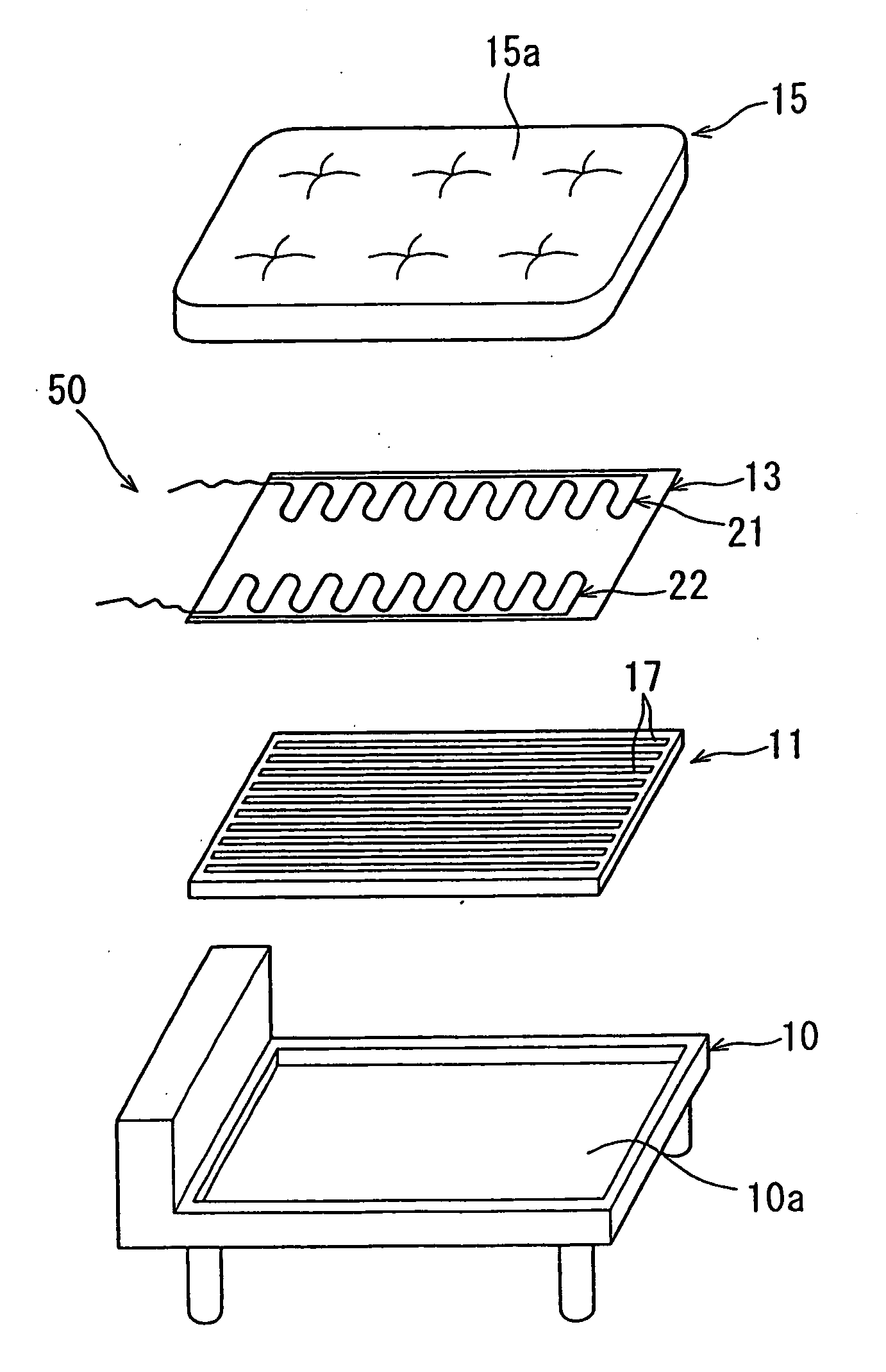
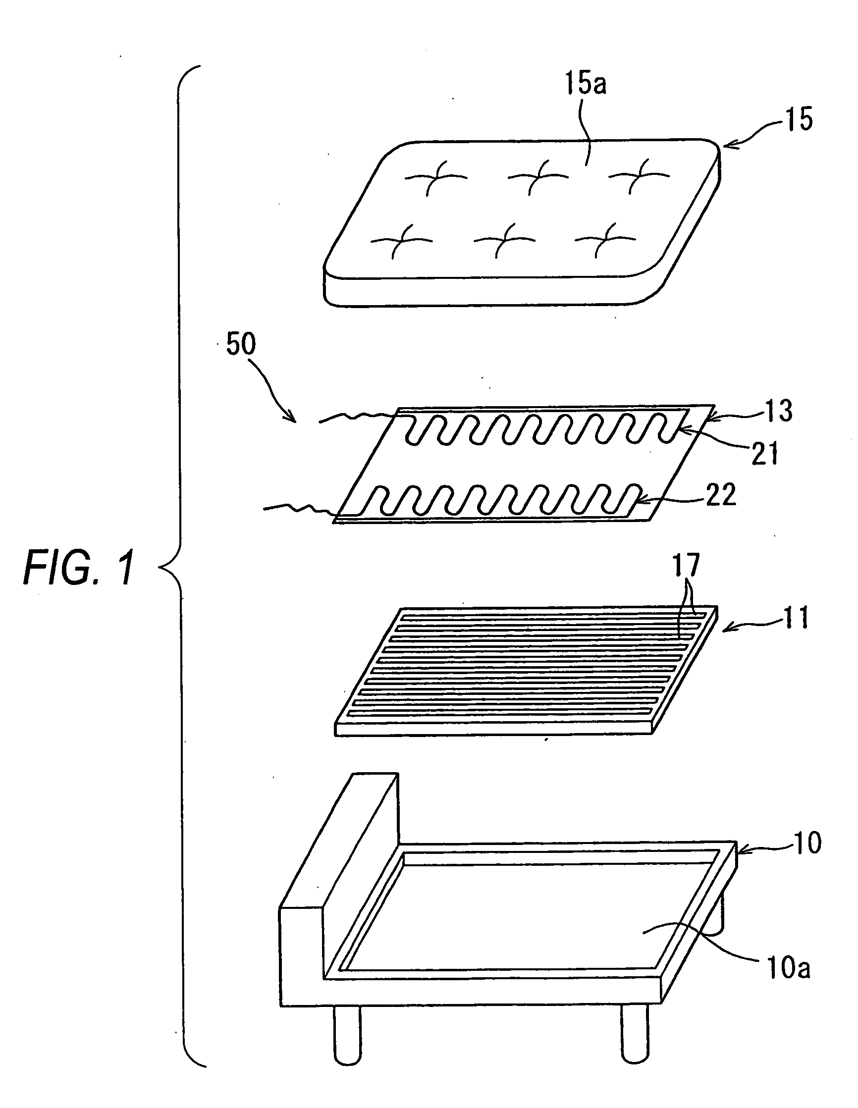
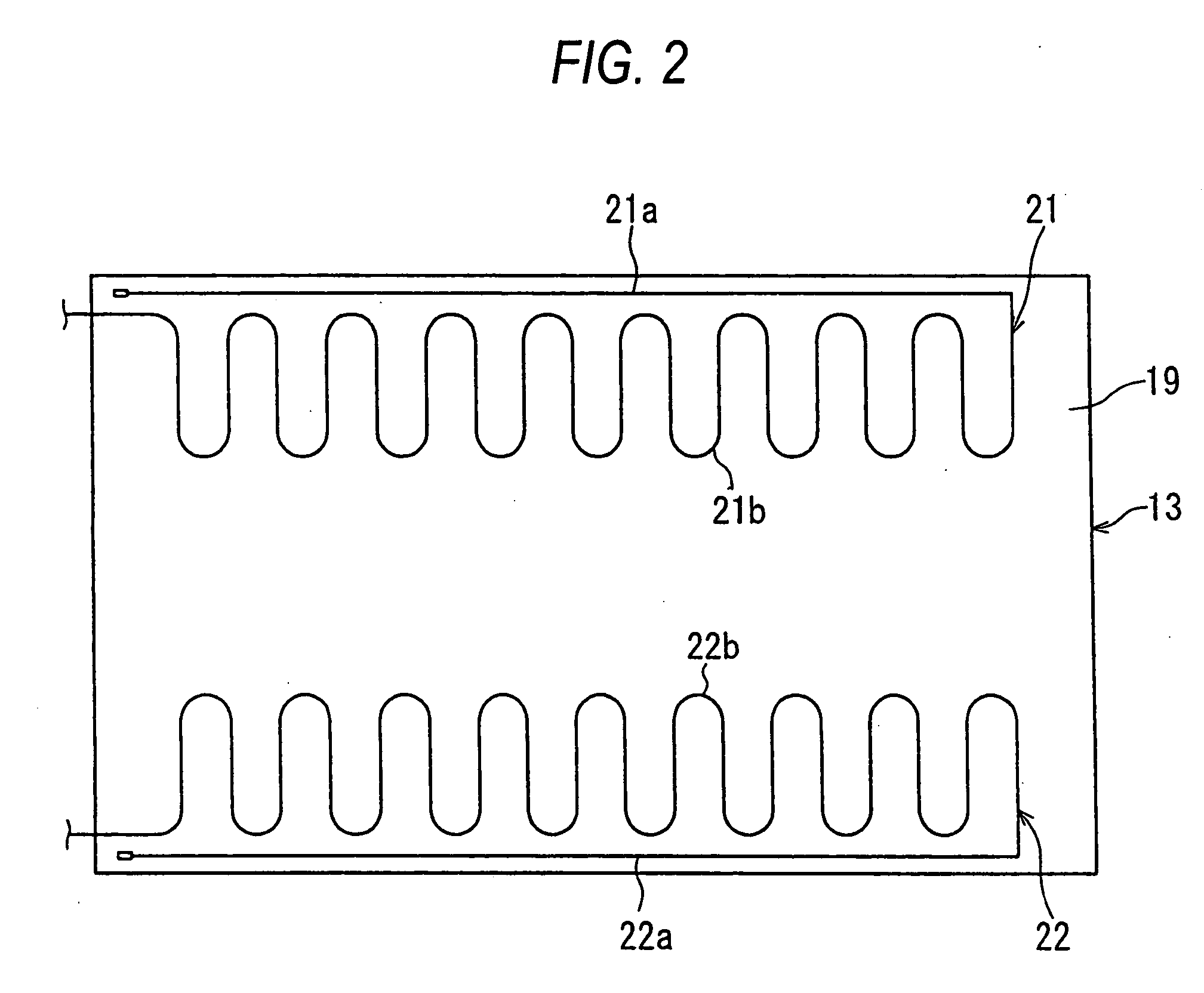
[0106]FIG. 1 is an exploded perspective view of the bed according to the embodiment 1, FIG. 2 is a plan view of a pressure sensitive sheet constituting the detection device of the apparatus, FIG. 3 is a plan view showing a pressure sensitive sensor and projection pieces of a projection sheet, FIG. 4 is a sectional view seen from a direction P in FIG. 3, and FIG. 5 is an exploded perspective view of the pressure sensitive sensor disposed on the pressure sensitive sheet.

[0107] As shown in FIG. 1, a bed (bed) 50 is configured in a manner that a projection sheet 11, a pressure sensitive sheet 13 and a mattress 15 are laminated on the panel surface 10a of a frame 10 in this order and assembled.

[0108] In the projection sheet 11, a plurality of projection pieces 17 are formed in parallel from one another along the longitudinal direction of the bed 50 on the upper surface side of the projection sheet. The projection pieces 17 are not limited to the configuration of the plural lines each f...

embodiment 2

[0155] The second embodiment of the invention will be explained with reference to FIGS. 13 to 27.

[0156] The second embodiment of the invention is explained based on FIGS. 13 to 27. FIG. 13 is an external perspective view of an electrically driven bed in which a pressure sensitive sensor is mounted. FIG. 14 is an external perspective view of the apparatus in which pressure sensitive sensors are disposed at portions of the surface end portions of a back raising panel portion and a knee raising panel portion. FIG. 15 is a schematic side view showing the positional relation between the bed and the side fence of the apparatus. FIG. 16 is a schematic perspective view showing a state where a bedded person touches the pressure sensitive sensor.

[0157] As shown in FIG. 13, the electrically driven bed 80 serving as a bed according to the second embodiment is arranged in a manner that the back raising panel portion 83 serving as a panel portion for a portion corresponding to the upper part of...

embodiment 3

[0200] Hereinafter, as a bed according to the third embodiment of the invention, a bed etc. capable of detecting heartbeats will be explained in detail with reference to drawings.

[0201]FIG. 28 is an exploded perspective view of the bed according to the third embodiment of the invention.

[0202]FIG. 29 is a perspective view showing the attachment state of a cord-shaped piezoelectric sensor of the apparatus.

[0203]FIG. 30 is a configuration diagram of the cord-shaped piezoelectric sensor of the apparatus.

[0204] Firstly, the cord-shaped piezoelectric sensor used in this embodiment will be explained briefly.

[0205] The cord-shaped piezoelectric sensor is a cable-shaped sensor using piezo element material practically developed by the applicant of the invention. The configuration of the piezoelectric sensor is shown in FIG. 30.

[0206] In FIG. 30, 126 depicts a cord-shaped piezoelectric sensor, which is configured in a manner that piezo element material 140 is covered around the circumfer...


PUM


Abstract

An object of the invention is to provide a bed which can surely detect the positional shift and heartbeat vibration of a bedded person while suppressing the increase of the cost and the degradation of the comfortability of a bed, and to provide a bed and an in-bed state detection method which can prevent the undesirable caught at the time of elevating the bed.
In order to detect the shift of a bedded person, a ratio of intensities between output signals from first pressure sensitive sensor 21 and a second pressure sensitive sensor 22 each having a cable shape is obtained. These sensors are disposed along the lying direction at the both end sides of a bedding surface 15a on which a bedded person lies, respectively. When the ratio is in a range of a predetermined shift state set in advance, it is determined that the positional shift of a bedded person on the bedding surface 15a occurs. Further, a low-repulsion urethane layer is provided within a bed pad thereby to detect the heartbeat vibration. Furthermore, the elevational driving of the panel portion is controlled in accordance with the output form the pressure sensitive sensor disposed on a bed.

Description

TECHNICAL FIELD [0001] The present invention relates a bed and an in-bed state detection method for monitoring the in-bed state of a person in the bed. BACKGROUND ART [0002] Recently, as a detection device for a bedded person in a bed, JP-A-7-88089, for example, discloses a device in which a pressure sensitive sensor for detecting whether a cared person as a bedded person is in bed or not and for detecting the change of the physical condition of the cared person is provided at a bed disposed in a hospital or various kinds of care facilities etc. This bed is arranged in a manner that many sensors each generating a small voltage due to the piezoelectric effect are disposed in the width direction of the bed on the upper surface of the bed on which the bedded person lies, and a row of the sensors thus disposed are arranged with a predetermined interval in the longitudinal direction of the bed. The voltages from these sensors are detected thereby to confirm whether a cared person is in b...

Claims


Application Information

Patent Timeline
Patent Type & Authority Applications(United States)
IPC IPC(8): G08B23/00A47C20/04A47C21/00A61B5/11A61G7/043A61G12/00
CPCA47C20/04A47C21/00A61B5/11A61B5/1115A61G2203/34A61B5/4806A61B5/6892A61B2562/0247A61B5/1126
Inventor UEDA, SHIGEKIOGINO, HIROYUKI
Owner PANASONIC CORP
Why Eureka
Try Eureka