Ultrasonic range finder

a range finder and ultrasonic technology, applied in the field of ultrasonic range finders, can solve the problems of inability to ensure the accuracy of measuring precision, the manufacturing cost of range finders is also very expensive, and the ultrasonic propagation speed is not a constant value, so as to achieve the effect of determining quickly and precisely, measuring a distance in different environments, and ensuring accuracy

Inactive Publication Date: 2007-01-11
NANJING CHERVON IND
View PDF23 Cites 11 Cited by
  • Summary
  • Abstract
  • Description
  • Claims
  • Application Information

AI Technical Summary

Benefits of technology

[0008] An object of the present invention is to provide an ultrasonic range finder to measure a distance quickly and precisely in different environments. The ultrasonic range finder detects an ultrasonic propagation time produced by the range finder within a constant reference distance to determine an ultrasonic propagation speed in the current environment. In this way, the determination of the ultrasonic propagation speed is not affected by atmospheric characteristics, and the ultrasonic propagation speed may be determined quickly and precisely in any environment so as to perform the distance measurement quickly and precisely.
[0009] Another object of the present invention is to provide an ultrasonic range finder, which can produce a visible mark on a target surface at a distance to be measured so that the user can align the ultrasonic beam with the target surface.
[0010] A further object of the present invention is to provide an ultrasonic range finder with a measuring object target so that the distance measurement can still be operated when there is no natural target surface at the distance to be measured.

Problems solved by technology

But the ultrasonic propagation speed is not a constant value and often varies with respect to changes in the environment.
However, it does not compensate for other environment factors and so the measuring precision can not be ensured.
However, such a sensor is very expensive causing the manufacturing cost of the range finder to also be very expensive.
Additionally, when the above-mentioned range finder is moved from one environment to another environment, the above-mentioned sensor will measure the atmospheric characteristics precisely only after a long time (maybe several minutes depending on the conditions) causing the results in the measuring time to be lengthened.
It is obvious that this limits the use of the disclosed ultrasonic range finder.

Method used


Image

  • Ultrasonic range finder
  • Ultrasonic range finder
  • Ultrasonic range finder

Examples


Embodiment Construction

[0022] While this invention is susceptible of embodiments in many different forms, there is shown in the drawings and will herein be described in detail preferred embodiments of the invention with the understanding that the present disclosure is to be considered as an exemplification of the principles of the invention and is not intended to limit the broad aspect of the invention to the embodiments illustrated.

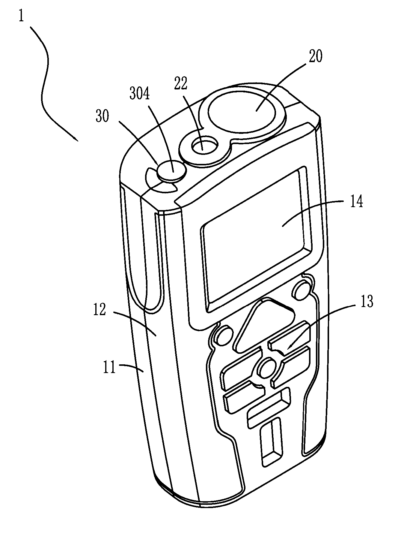
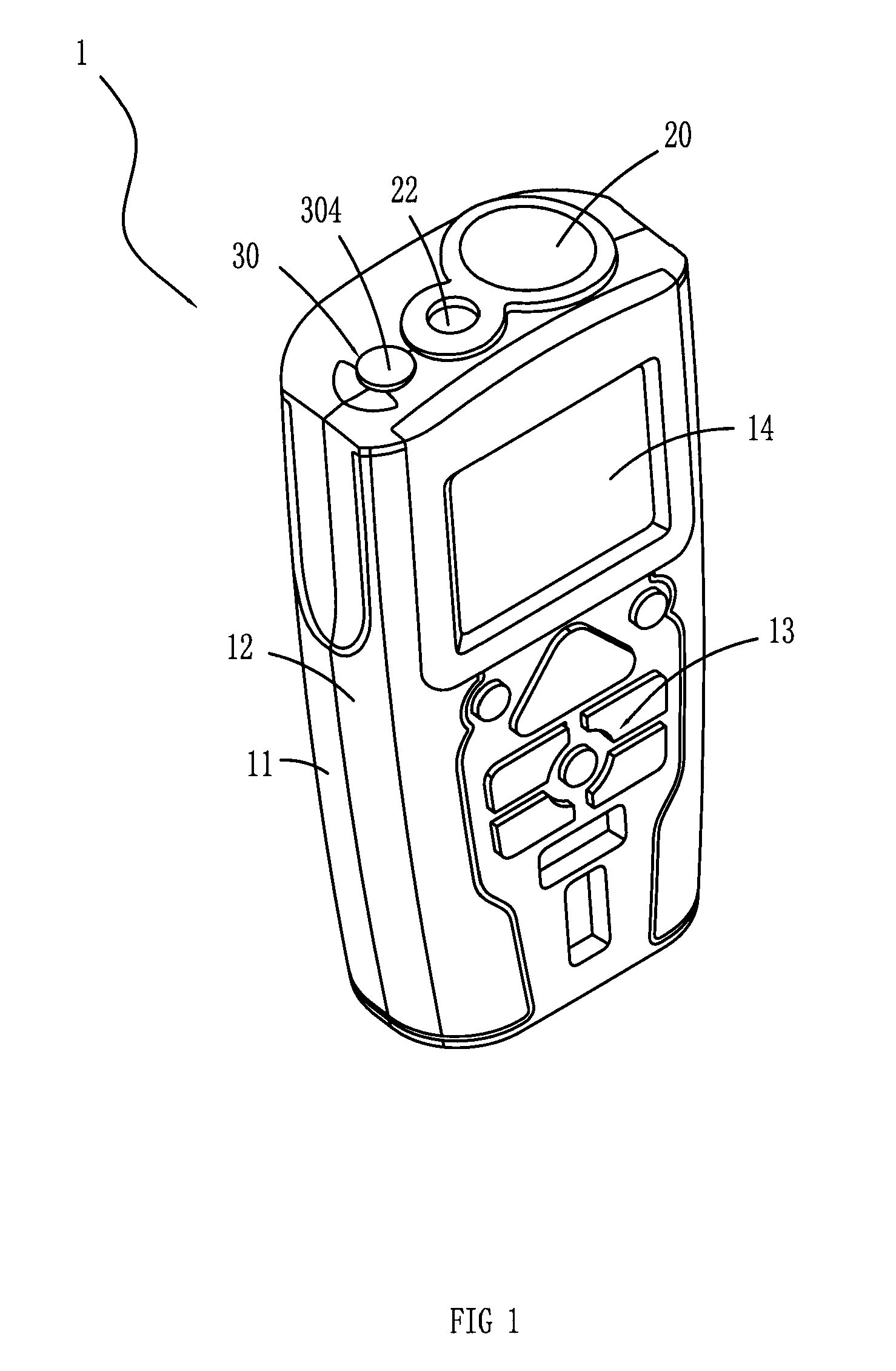
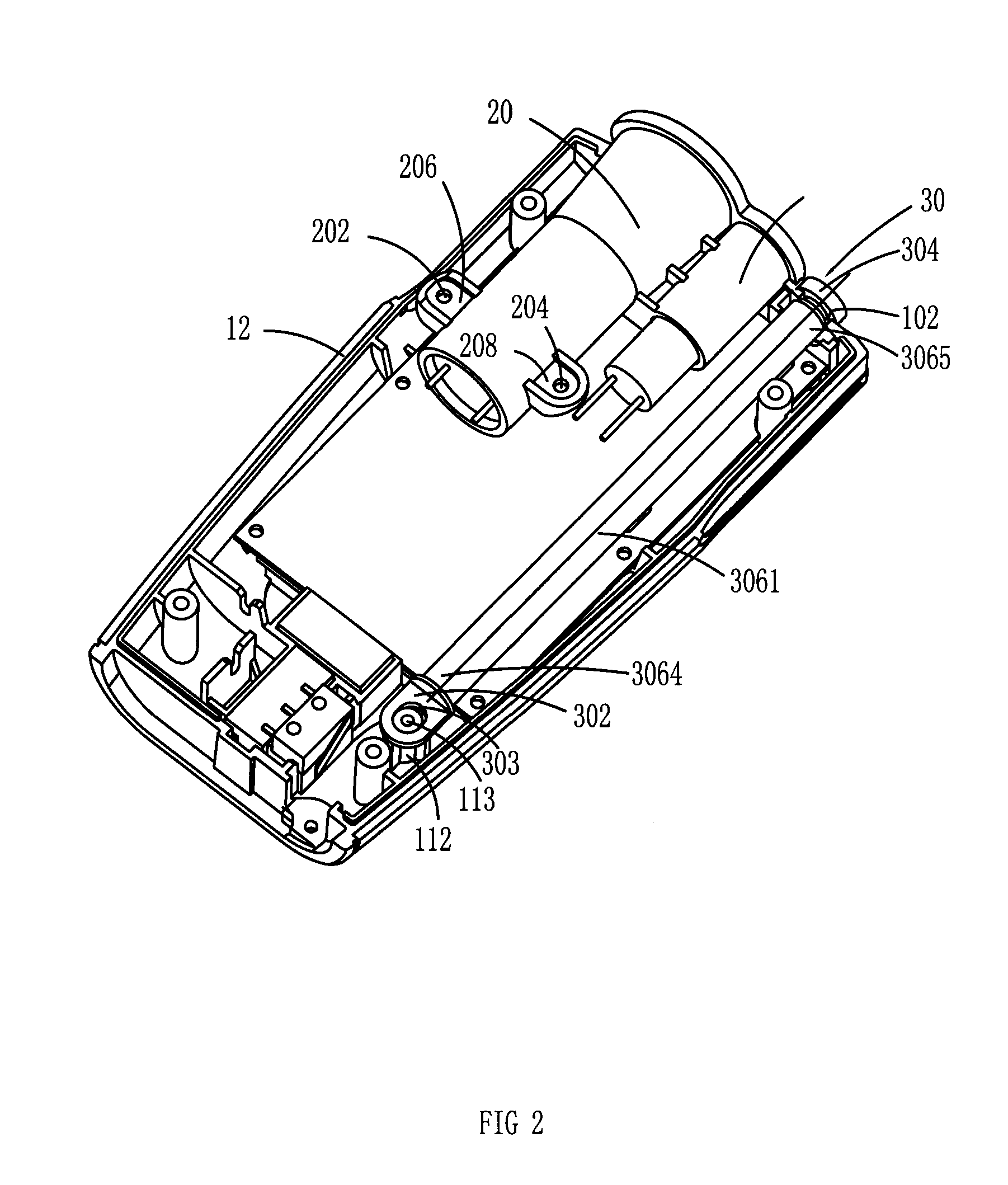
[0023] As shown in FIG. 1 to FIG. 2, a preferred embodiment of the present invention provides an ultrasonic range finder 1, which includes a casing comprising a right casing 11 and a left casing 12, an ultrasonic transmitting / receiving unit 20, a signal processing circuit (not shown in Figs), a group of operation buttons 13, a display unit 14 for displaying the result of a distance measurement, and a calibration rod 30. With reference to FIG. 2, a flange 206 and a flange 208 are protruded respectively from two sides of one end of the ultrasonic transmitting / receiving unit 20....


PUM


Abstract

The present invention is intended to provide an ultrasonic range finder to measure a distance quickly and precisely under different environments. The ultrasonic range finder comprises a casing, an ultrasonic transmitting / receiving unit, a signal processing circuit connected electrically with the ultrasonic transmitting / receiving unit in the casing, a group of operation buttons on the casing and a display unit. The ultrasonic range finder further comprises a calibration rod to provide a constant reference distance. The calibration rod includes a first end connected to the casing. The calibration rod further includes a second end extendable outwardly relative to the casing and a body between the first and the second ends. By measuring a propagation time of an ultrasonic signal within the constant reference distance an ultrasonic propagation speed can be determined quickly and precisely and thereby perform the distance measurement quickly and precisely without being affected by changes in the environment.

Description

CROSS-REFERENCE TO RELATED APPLICATIONS [0001] This application claims priority to Chinese Application No. 200520073449.7, filed on Jul. 8, 2005, the entire disclosure of which is incorporated herein by reference. Priority to this application is claimed under 35 U.S.C. 119, 120 and / or 365. FEDERALLY SPONSORED RESEARCH OR DEVELOPMENT [0002] None. TECHNICAL FIELD [0003] The invention relates to a range finder, and more particularly, to an ultrasonic range finder that determines a measured distance through detecting an ultrasonic propagation time within the measured distance. BACKGROUND OF THE INVENTION [0004] Currently, ultrasonic range finders are widely used in many fields such as in engineering. Usually, the ultrasonic range finders detect an ultrasonic propagation time within a measured distance, and then the measured distance can be obtained by multiplying the ultrasonic propagation time by an ultrasonic propagation speed. But the ultrasonic propagation speed is not a constant va...

Claims


Application Information

Patent Timeline
Patent Type & Authority Applications(United States)
IPC IPC(8): G01S15/00
CPCG01S7/52004Y10S367/902G01S15/08
Inventor YANG, DEZHONG
Owner NANJING CHERVON IND
Why Eureka
Try Eureka