Apparatus and method of on-channel repeater

a technology applied in the field of on-channel repeater and apparatus, can solve the problems of ineffective frequency utilization of conventional repeater, limited transmission power of on-channel repeater, and noise signals that cannot be eliminated by equalizers

Inactive Publication Date: 2007-02-22
ELECTRONICS & TELECOMM RES INST +1
View PDF2 Cites 12 Cited by
  • Summary
  • Abstract
  • Description
  • Claims
  • Application Information

AI Technical Summary

Benefits of technology

[0021] It is, therefore, an object of the present invention to provide an on-channel repeater and method, for repeating the same output signal as an input signal of the on-channel repeater over an on-channel by converting a RF broadcast signal transmitted from a main transmitter into a baseband signal, removing noise and multi-path signals generated due to a transmission channel between the main transmitter and the on-channel repeater and a feedback signal generated due to low isolation of transmission / reception antennas, from the converted baseband signal through a high performance equalizer, and then again converting the baseband signal into a RF broadcast signal.

Problems solved by technology

However, since the conventional repeater of FIG. 1 assigns a different frequency to each of the repeaters 102 to 105 to solve the weak signal problem for the signal received from the main transmitter 101 or to increase the broadcast zone, the conventional repeater is inefficient in frequency utilization in that each of the repeaters 102 to 105 uses a plurality of frequency bands which in turn utilizes a large amount of frequency resources.
These noise signals cannot be eliminated by the equalizer.
3 to 6 have drawbacks in that the transmission power of the on-channel repeater is limited due to the feedback signal generated due to the low isolation of the transmission / reception antennas.
However, since the conventional demodulation / modulation on-channel repeater in FIG. 6 includes a FEC decoding unit and a FEC encoding unit, the time delay in the on-channel repeater is increased from few microseconds to few milliseconds.

Method used


Image

  • Apparatus and method of on-channel repeater
  • Apparatus and method of on-channel repeater
  • Apparatus and method of on-channel repeater

Examples


Embodiment Construction

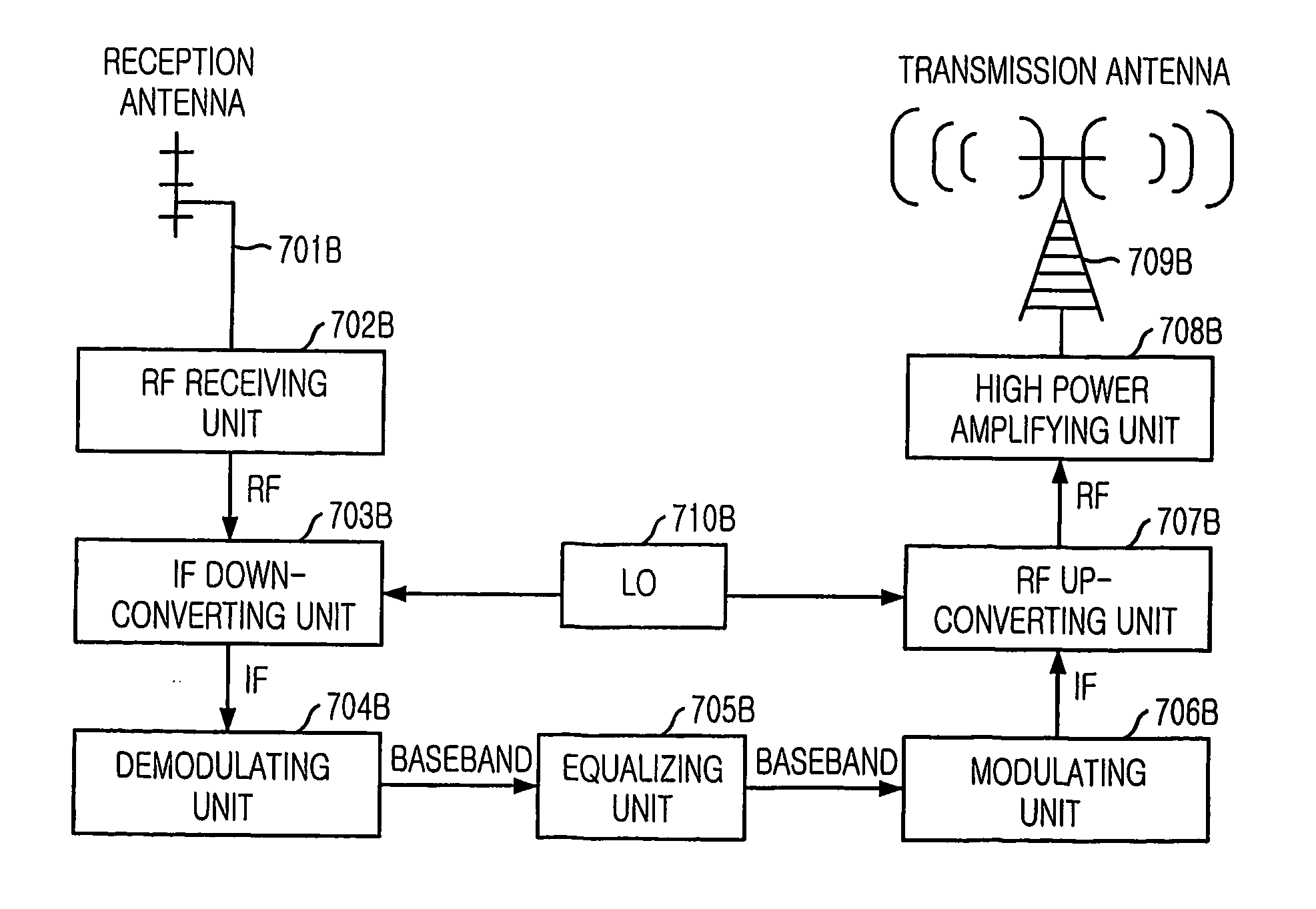
[0041]FIG. 7 is a diagram illustrating an on-channel repeater in accordance with a preferred embodiment of the present invention.

[0042] As shown, the on-channel repeater includes an RF receiving unit 701A for receiving a radio frequency (RF) signal, a demodulating unit 702A for converting the RF signal into a baseband signal, an equalizing unit 703A for compensating distortion of the baseband signal, a modulating unit 704A for converting the signal from the equalizing unit 703A to an RF signal, and an RF transmitting unit 705A for transmitting the RF signal.

[0043] Hereinafter, the on-channel repeater will be described in detail.

[0044] The RF receiving unit 701A receives a radio frequency (RF) signal from a main transmitter. The demodulating unit 702A converts the RF signal into a baseband signal. The equalizing unit 703A removes noise and multi-path signals generated between the main transmitter and the on-channel repeater and a feedback signal from the converted baseband signal....


PUM


Abstract

Provided is an on-channel repeater and method thereof. The on-channel repeating apparatus includes: a receiving unit for receiving a Radio Frequency (RF) broadcast signal; a demodulating unit for converting the RF signal into a baseband signal; an equalizing unit for equalizing the baseband signal to generate an equalized baseband signal; a modulating unit for converting the equalized baseband signal into an RF signal; and a transmitting unit for transmitting the RF signal.

Description

TECHNICAL FIELD [0001] The present invention relates to an on-channel repeater and method thereof; and, more particularly, to an on-channel repeater and method thereof, in which a Radio Frequency (Hereinafter, referred to as “RF”) broadcast signal transmitted from a main transmitter is converted into a baseband signal. Noise and multi-path signals generated due to a transmission channel between the main transmitter and the on-channel repeater and a feedback signal generated due to low isolation of transmission / reception antennas of the on-channel repeater are removed from the baseband signal by using an equalizer, and the baseband signal is again converted into a RF broadcast signal such that the same output signal as an input signal of the on-channel repeater is repeated over an on-channel. BACKGROUND ARTS [0002] Generally, to provide a broadcasting service, a main transmitter and a repeater are disposed depending on a peripheral topography and natural feature, and depending on a s...

Claims


Application Information

Patent Timeline
Patent Type & Authority Applications(United States)
IPC IPC(8): H04B3/36H04N7/015H04B1/10H04H20/06H04L27/06H04L27/14H04N5/21H04N5/38H04N5/455
CPCH04H20/06H04N5/211H04N5/38H04B7/15564H04N7/015
Inventor PARK, SUNG-IKLEE, YONG-TAESEO, JAE-HYUNKIM, SEUNG-WONLEE, SOO-IN
Owner ELECTRONICS & TELECOMM RES INST
Why Eureka
Try Eureka