Display device

a technology of display device and display screen, which is applied in the direction of projectors, instruments, optics, etc., can solve the problem of difficult random change of pitch, and achieve the effect of convenient manufactur

Active Publication Date: 2007-03-08
SUNTECHOPT
View PDF4 Cites 11 Cited by
  • Summary
  • Abstract
  • Description
  • Claims
  • Application Information

AI Technical Summary

Benefits of technology

[0020] In case of a display device in which the pitch of the repeating unit of the lens is smaller than the width of the optical transparency base unit and the widths of them are not set to the integral multiplication, the display device can preferably prevent moiré fringes by setting the widths of the optical transparenc

Problems solved by technology

However, to change the pitch rand

Method used


Image

  • Display device
  • Display device
  • Display device

Examples


first embodiment

A First Embodiment

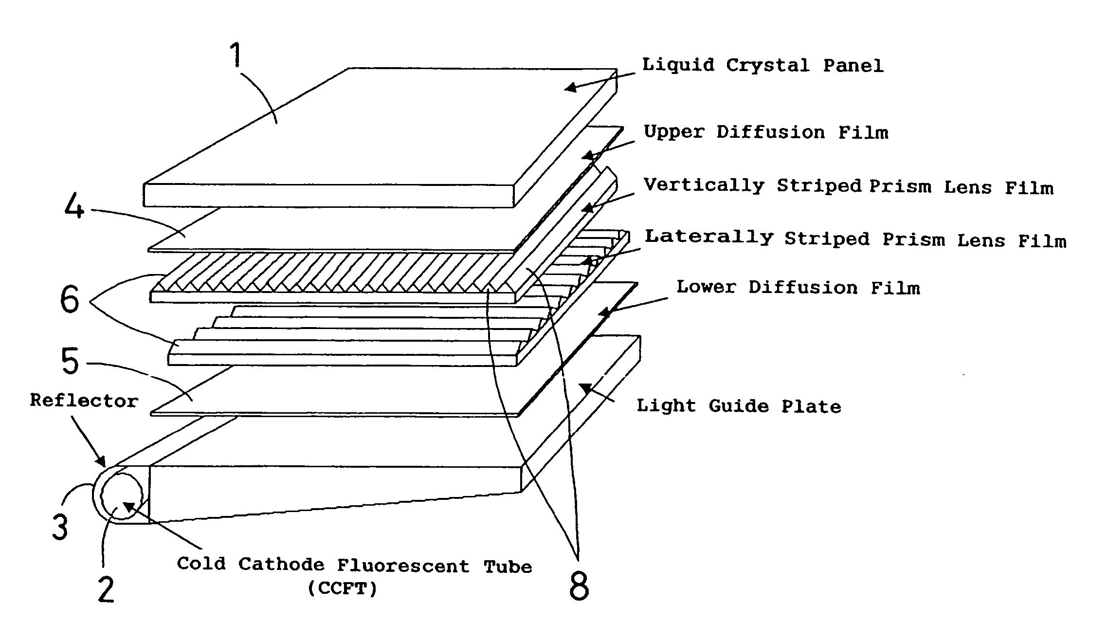
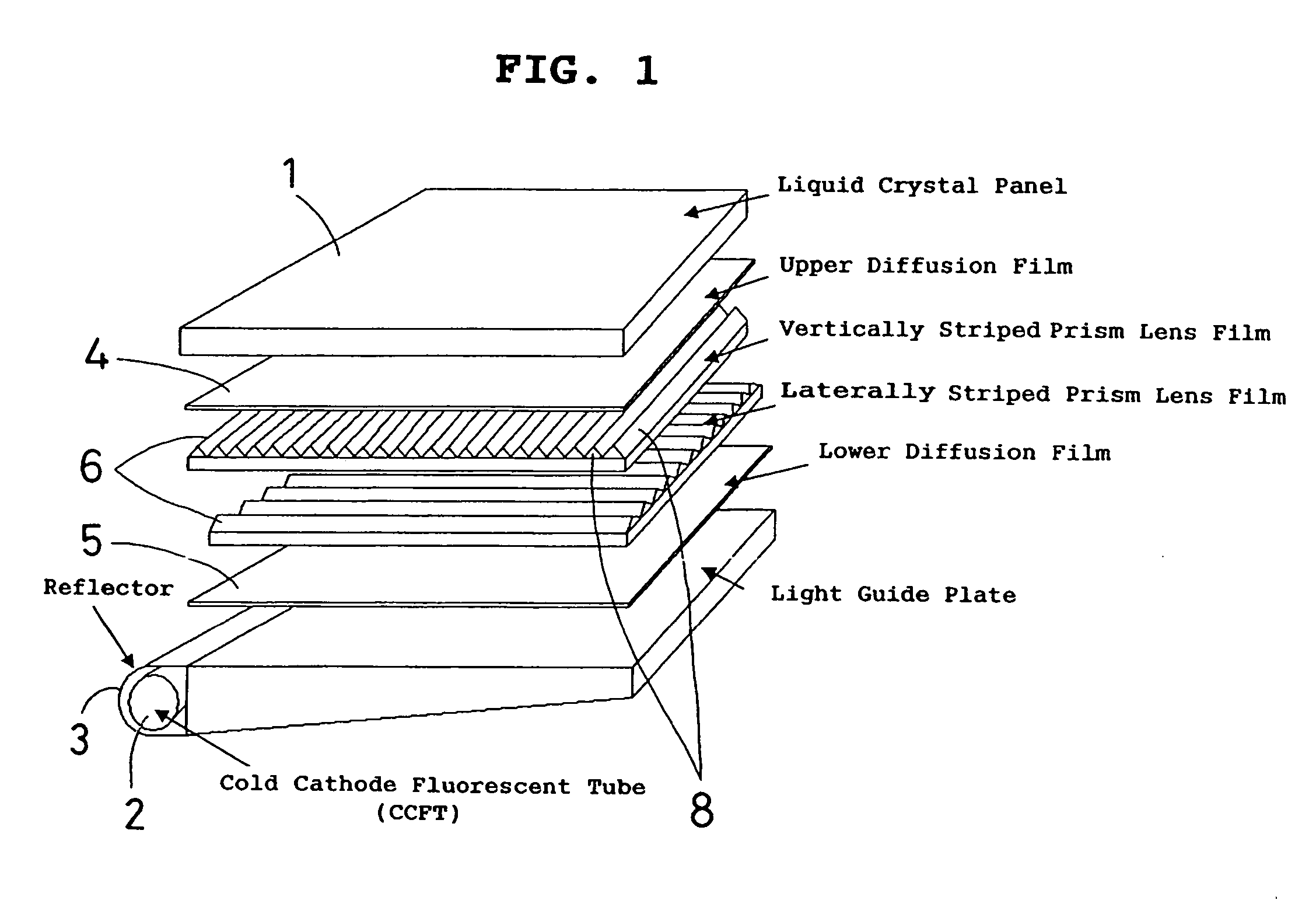
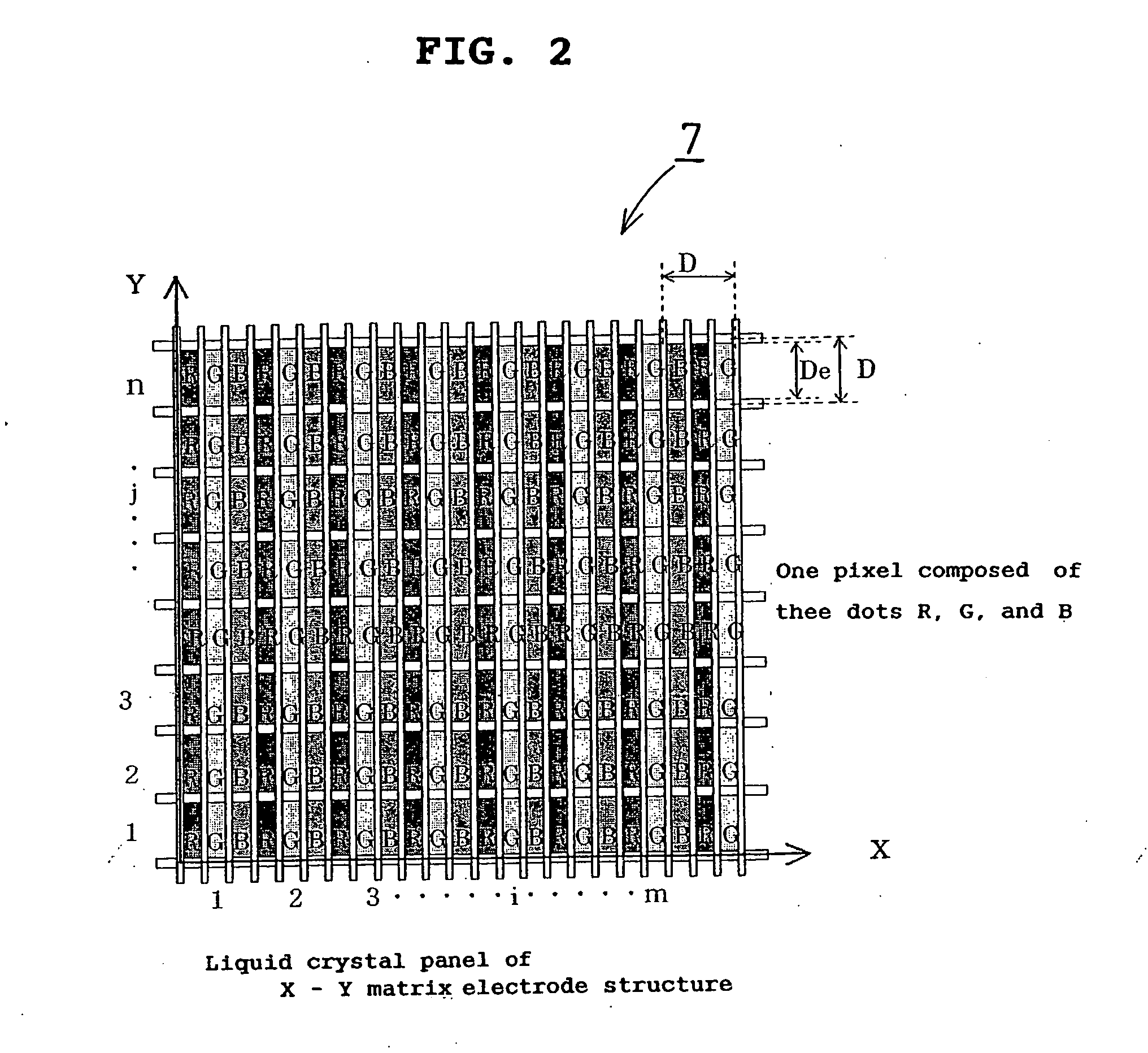
[0037] As shown in FIGS. 1 to 6, the display device of this embodiment is formed in such a manner that a lens film part 6 having a prism-array-shape made of vertically striped peaks and valleys (see FIG. 3) and a lens film part 6 having a prism-array-shape made of laterally striped peaks and valleys are arranged between a liquid crystal panel 1 having color filters (R, G, and B) (see FIG. 2) and a backlight (a cold cathode fluorescent tube 2 and a reflector 3) via an upper diffusion film 4 and a lower diffusion film 5 so as to improve luminance.

[0038] As shown in FIG. 4 and FIG. 6, an electrode or a black mask (an optical no-transparency base unit) corresponding to a red pixel (R, a width dr) of color filters (R, G, B) is defined as dMr; an electrode or a black mask (an optical no-transparency base unit) corresponding to a green pixel (G, a width dg) thereof is defined as dMg; and an electrode or a black mask (an optical no-transparency base unit) corresponding to...

second embodiment

A Second Embodiment

[0049] A display device of the second embodiment is different from the first embodiment mainly in that pixels are aligned in a so-called delta alignment.

[0050] The display device according to this embodiment (see FIG. 1) is formed in such a manner that a lens film part 6 having a prism-array-shape made of vertically striped peaks and valleys (see FIG. 3) and a lens film part 6 having a prism-array-shape made of laterally striped peaks and valleys are arranged between a liquid crystal panel 1 having color filters (R, G, and B) (see FIG. 7) and a backlight (a cold cathode fluorescent tube 2 and a reflector 3) via an upper diffusion film 4 and a lower diffusion film 5 so as to improve luminance.

[0051] Then, an image control panel part 7 (see FIG. 7) is continuously provided with combination base units (D=Dex+dMx=Dey+dMy) including optical transparency base units (Dex=Dey) of color filters (R, G, B) and optical no-transparency base units (dMx=dMy) of electrodes or b...

third embodiment

A Third Embodiment

[0060] A display device of the third embodiment is different from the first embodiment mainly in that the transparency base unit and the lens film part are laminated so as to have a crossing angle θ.

[0061] The display device according to this embodiment (see FIG. 1) is formed in such a manner that a lens film part 6 having a prism-array-shape made of vertically striped peaks and valleys (see FIG. 8) and a lens film part 6 having a prism-array-shape made of laterally striped peaks and valleys are arranged between a liquid crystal panel 1 having color filters (R, G, and B) (see FIG. 2) and a backlight (a cold cathode fluorescent tube 2 and a reflector 3) via an upper diffusion film 4 and a lower diffusion film 5 so as to improve luminance.

[0062] As shown in FIG. 4, an electrode or a black mask (an optical no-transparency base unit) corresponding to a red pixel (R, a width dr) of color filters (R, G, B) is defined as dMr; an electrode or a black mask (an optical no-...


PUM


Abstract

An object of the present invention is to provide a display device that can be manufactured more easily than the conventional one. To accomplish this object, an image control panel part (7) which is continuously provided with combination base units including optical transparency base units and optical no-transparency base units, and a lens film pail (6) which is continuously provided with repeating units of lenses (8) are laminated in a direction of light transmission, and either one width of the optical transparency base unit or a pitch of the repeating unit of the lens is set so as to be the integral multiplication of the other width. Since the moiré fringes can be prevented by setting either one width of the optical transparency base unit or the pitch of the repeating unit of the lens 8 so as to be the integral multiplication of the other width, it is not always necessary for the display device of the present invention to change a pitch of the mold for manufacturing the lens film part 6 randomly.

Description

BACKGROUND OF THE INVENTION [0001] 1. Field of the Invention [0002] The present invention relates to a display device such as a liquid crystal panel of a personal computer, a TV set and others. [0003] 2. Description of the Related Art [0004] Conventionally, there has been a display device such as a liquid crystal panel. (For example, Patent document 1) [0005] As shown in FIG. 13, this display device includes a light guide plate 1, a diffusion film 2, a translucent film 3 (for enhancing a luminance), one surface of which is a substantially flat and another surface has a parallel prismatic shape, a diffusion film 6, and a liquid crystal panel 4, and these are laminated in this order. [0006] Further, other proposals are made for the translucent film having the prismatic shape. (For example, Patent document 2) As shown in FIG. 14, an optical film 60 (equivalent to the above-mentioned translucent film) has a structural surface 64 and a surface 62 opposed to the structural surface 64. The...

Claims


Application Information

Patent Timeline
IPC IPC(8): G03B21/14G03B21/00
CPCG02F2001/133607G02B6/0053G02F1/133607G02F1/1335
Inventor KANATANI, YOSHIHARUSHIMAMURA, YUKIO
Owner SUNTECHOPT
Why Eureka
Try Eureka