Cooking apparatus

a technology of cooking apparatus and cooking chamber, which is applied in the field of cooking apparatus, can solve the problems of excessive consumption of energy and the inability to achieve a completely uniform temperature distribution in the cooking chamber, and achieve the effect of evenly distributed high-temperature air

Active Publication Date: 2007-05-03
SAMSUNG ELECTRONICS CO LTD
View PDF3 Cites 20 Cited by
  • Summary
  • Abstract
  • Description
  • Claims
  • Application Information

AI Technical Summary

Benefits of technology

[0009] Accordingly, it is an aspect of the present invention to provide a cooking apparatus in which a single driving fan and a plurality of driven fans are provided to effectively agitate high-temperature air, whereby the high-temperature air can be evenly distributed into the overall space of a cooking chamber.

Problems solved by technology

However, the conventional cooking apparatus has a problem in that it consumes excessive energy since the two blowing fans are operated by use of different motors to reduce the temperature difference in the cooking chamber.
Further, based upon the asymmetric structure of the conventional cooking apparatus in which the two blowing fans are arranged adjacent to each other, it is impossible to achieve a completely even temperature distribution in the cooking chamber.

Method used


Image

  • Cooking apparatus
  • Cooking apparatus
  • Cooking apparatus

Examples


Embodiment Construction

[0034] Reference will now be made in detail to exemplary embodiments of the present invention, examples of which are illustrated in the accompanying drawings, wherein like reference numerals refer to like elements throughout. The embodiments are described below to explain the present invention by referring to the figures.

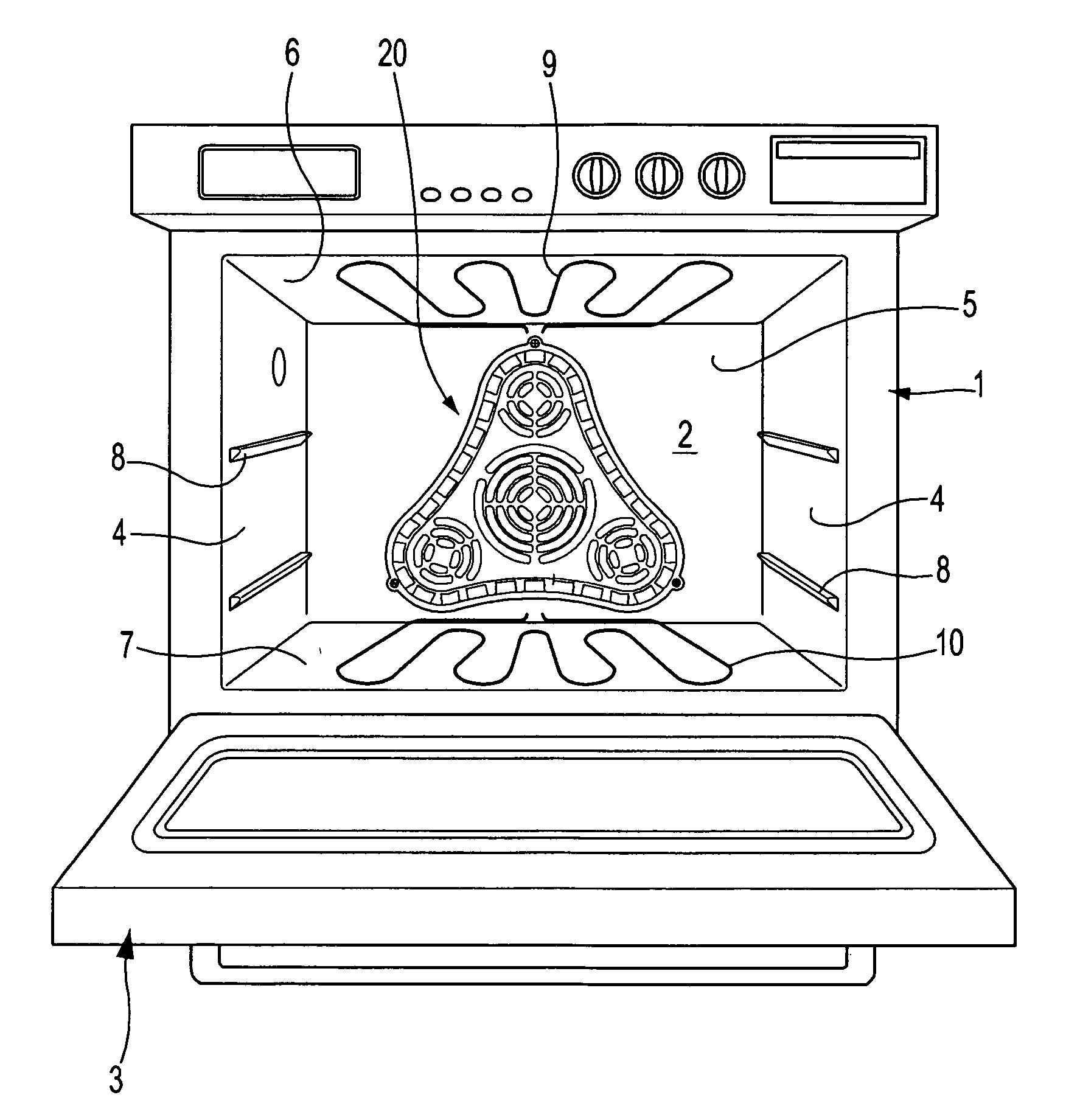
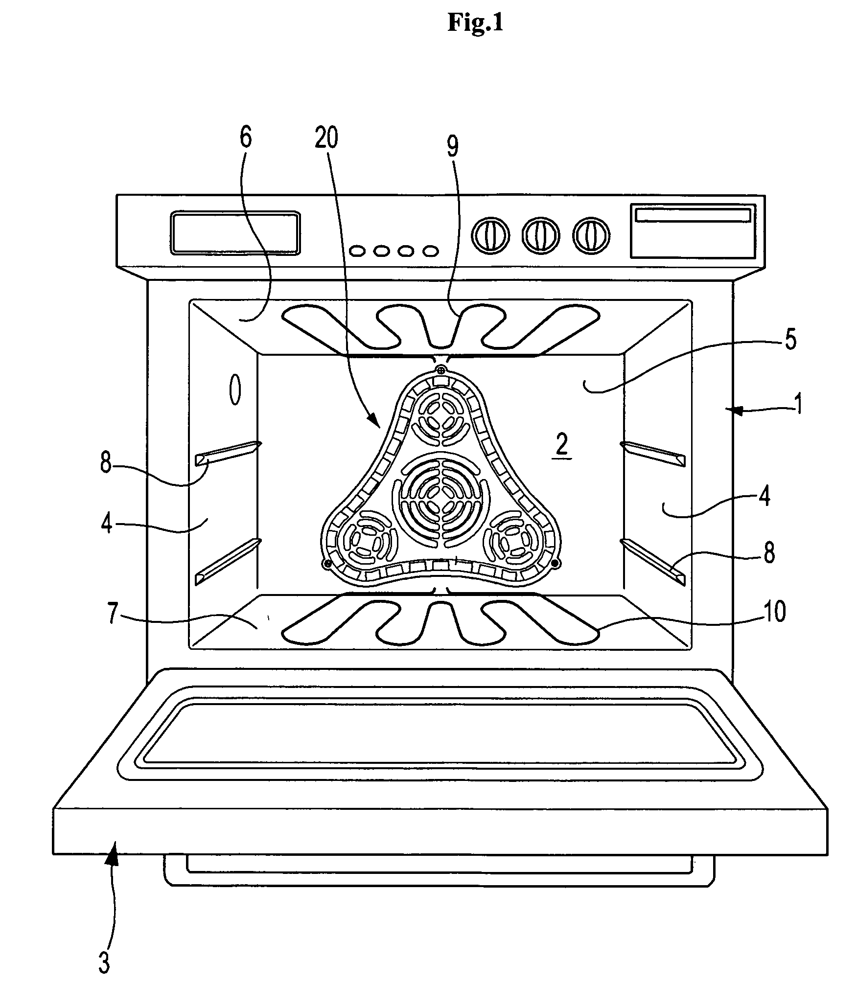
[0035]FIG. 1 is a front view illustrating a cooling apparatus in accordance with an embodiment of the present invention. As shown in FIG. 1, the cooking apparatus of the present invention comprises a housing 1 internally provided with a cooking chamber 2 having an open front side, and a door 3 hinged to the front side of the housing 1 to open or close the cooking chamber 2. The housing 1 and the door 3 form an outer appearance of the cooking apparatus.

[0036] A plurality of rails 8 are arranged on opposite side walls 4 of the cooking chamber 2 so that the rails 8 are vertically spaced apart from each other. The rails 8 serve to support racks (not shown), on which f...


PUM


Abstract

A cooking apparatus to effectively agitate and evenly distribute high-temperature air into a cooking chamber by use of a single driving fan and a plurality of driven fans. The cooking apparatus includes the cooking chamber, the driving fan arranged at a rear wall of the cooking chamber, a convection heater to surround the driving fan, the plurality of driven fans arranged on a circumference of the driving fan, and a fan cover having a plurality of suction holes and discharge holes. The driving fan is connected with a drive motor to rotate in accordance with an operation of the drive motor. The driven fans rotate by use of air streams generated when the driving fan rotates. The high-temperature air is evenly agitated in accordance with the rotation of the driven fans to be distributed into the cooking chamber via the discharge holes in all directions.

Description

CROSS-REFERENCE TO RELATED APPLICATIONS [0001] This application claims the benefit of Korean Patent Application No. 2005-103253, filed on Oct. 31, 2005 in the Korean Intellectual Property Office, the disclosure of which is incorporated herein by reference. BACKGROUND OF THE INVENTION [0002] 1. Field of the Invention [0003] The present invention relates to a cooking apparatus. More particularly, to a cooking apparatus in which a single driving fan and a plurality of driven fans are provided to effectively agitate high-temperature air, whereby the high-temperature air is evenly distributed into the overall space of a cooking chamber. [0004] 2. Description of the Related Art [0005] Generally, a conventional cooking apparatus includes a heater and a blowing fan. When the blowing fan suctions air inside a cooking chamber, the heater heats the suctioned air to high-temperature air. After that, the blowing fan discharges the high-temperature air into the cooking chamber. As this air suctio...

Claims


Application Information

Patent Timeline
Patent Type & Authority Applications(United States)
IPC IPC(8): A21B1/22
CPCF24C15/325A47J27/00F24C1/00
Inventor SUNG, HAN JUNHAN, DAE SUNGKWON, YONG HYUNLEE, TAE-UKJANG, SEONG-DEOGCHO, PUNG YEUNKANG, HAN SEONG
Owner SAMSUNG ELECTRONICS CO LTD
Why Eureka
Try Eureka