Eureka AIR delivers breakthrough ideas for toughest innovation challenges, trusted by R&D personnel around the world.

Liquid container and inkjet recording apparatus

a liquid container and inkjet technology, applied in printing and other directions, can solve the problems of increasing the size of the recording apparatus, the space occupied by the ink tank, and the power required to move the carriage, so as to reduce the variation in the concentration of liquid and efficiently agitate the ink

Active Publication Date: 2007-03-15
CANON KK
View PDF3 Cites 2 Cited by
  • Summary
  • Abstract
  • Description
  • Claims
  • Application Information

AI Technical Summary

Benefits of technology

[0022] The present invention is directed to a liquid container and a recording apparatus allowing the acquisition of a satisfactory image by efficiently agitating ink stored in the liquid container and reducing variations in concentration of the liquid occurring after the liquid container is left standing for a long period of time using an inexpensive structure.
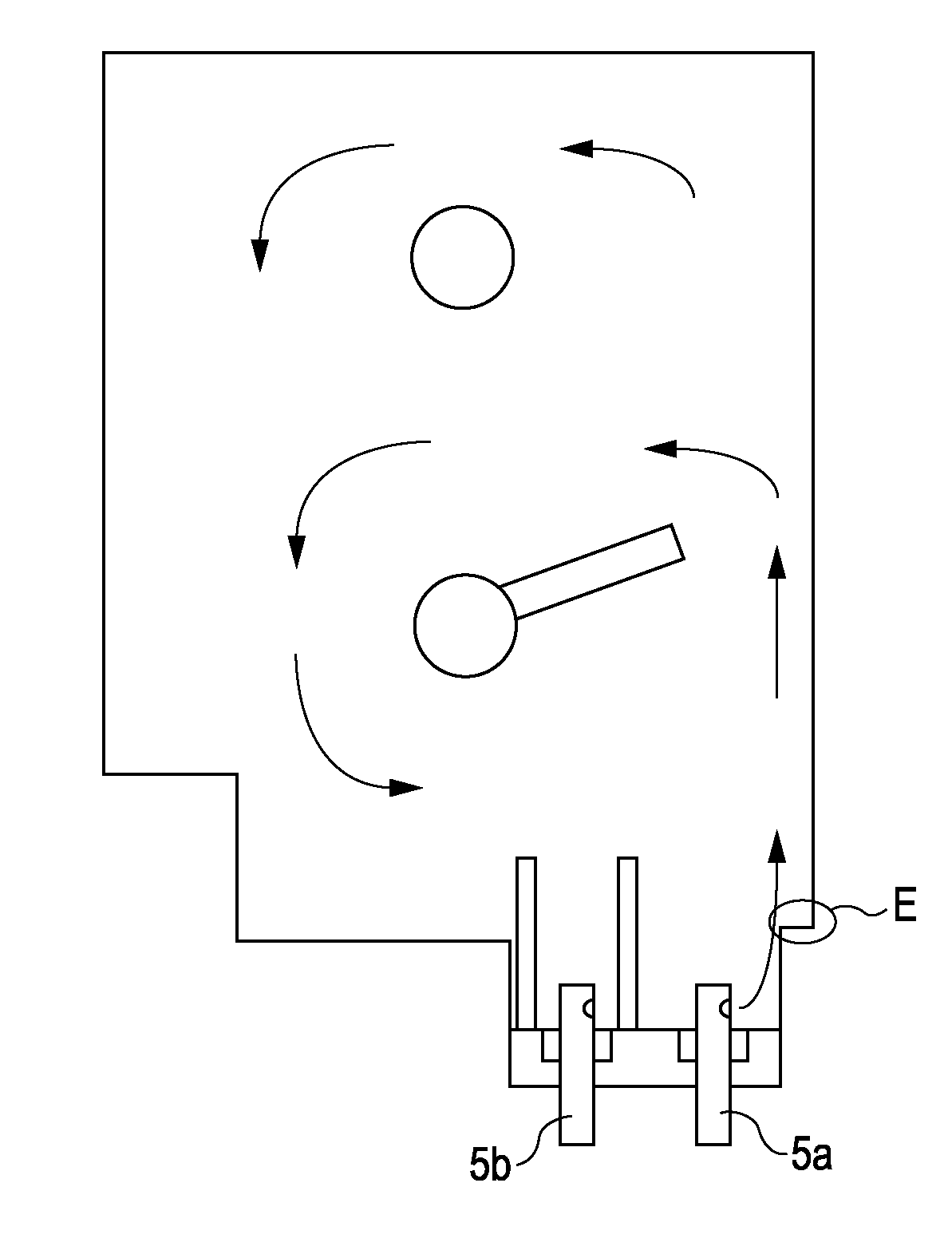
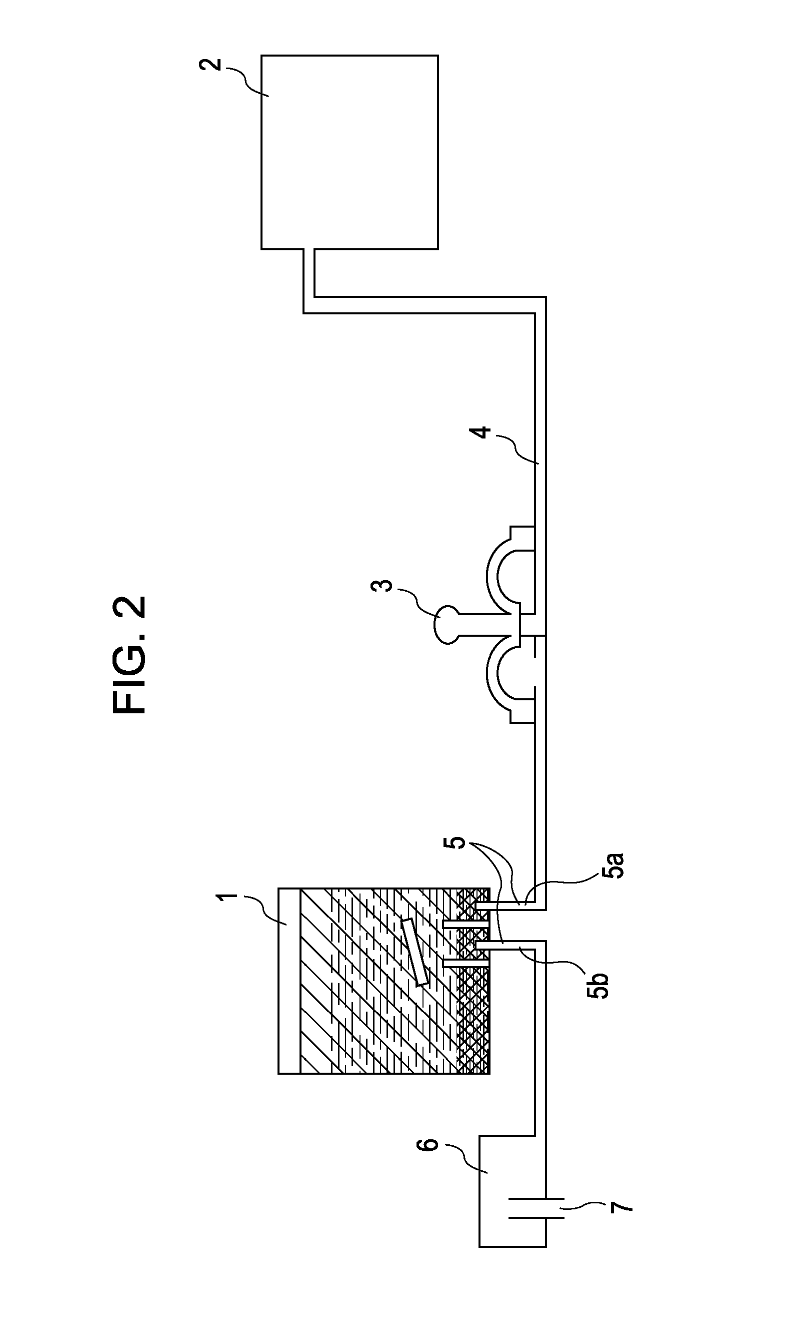
[0023] According to a first aspect of the present invention, a liquid container capable of being detachably mounted on an inkjet recording apparatus including a liquid supply tube facilitating supplying liquid to the liquid container, an air introduction tube facilitating introducing air to the liquid container, and a valve configured to introduce ink into and eject ink from the liquid container by enabling and disabling ink communication along a communication path in the liquid supply tube is provided. The liquid container includes a liquid storage chamber configured to store recording liquid containing pigment, a liquid supply unit disposed at a bottom of the liquid storage chamber and adjacent to a first side of the liquid storage chamber in a state in which the liquid container is used, the liquid supply unit being connectable to the liquid supply tube, an air introduction unit disposed at the bottom of the liquid storage chamber and connectable to the air introduction tube, and a structure configured to restrict an upward flow of ink introduced into the liquid storage chamber from the liquid supply unit toward the first side, the structure being disposed in a direction that intersects a vertical direction.
[0024] According to a second aspect of the present invention, an inkjet recording apparatus includes a recording head configured to discharge ink and perform recording, a liquid supply tube facilitating supplying liquid to a liquid storage chamber, an air introduction tube facilitating introducing air so as to replace liquid to be supplied, a liquid container detachably mounted on the inkjet recording apparatus, the liquid container storing ink containing pigment in the liquid storage chamber, the liquid container including a liquid supply unit connected to the liquid supply tube and an air introduction unit connected to the air introduction tube, and a valve configured to introduce ink into and eject ink from the liquid container by enabling and disabling ink communication along a communication path in the liquid supply tube. The liquid container further includes a structure configured to restrict an upward flow of ink introduced by the valve into the liquid storage chamber toward a first side of the liquid storage chamber, the structure being disposed in a direction that intersects a vertical direction.
[0025] Since a flow of ink diffuses precipitated ink efficiently, there is no need to waste ink. Additionally, since highly concentrated ink is not discarded, the overall concentration of ink within the ink tank is not reduced. Controlling an upward flow of ink using a structure for restricting a flow of ink disposed on the ink tank enables a small amount of ink flowing in and out the ink tank to diffuse precipitated ink. This can reduce the load on a driving source and a space for temporarily holding ink. As a result, the size of the main body of the apparatus can be reduced, and the cost can be suppressed.

Problems solved by technology

However, the cartridge replacement type has a limitation of providing an ink tank on a carriage up to a certain size.
If a large ink tank is provided to reduce the frequency of replacement of the ink tank, a space occupied by the ink tank is significantly large.
This increases the size of a recording apparatus and the power required to move the carriage.
As a result, a very large power source is required, and other various problems arise.
However, the pigment ink has a problem in which pigment precipitates on the bottom of the ink tank when it is left standing for a long time and thus ink concentration varies depending on the location within the ink tank.
For a recording apparatus such as a wide format printer, a significantly large ink tank capacity is desired in order to reduce running costs, and in the case of pigment ink, concentration variations are a very serious problem that might decrease image quality.
However, for the exemplary agitation method using bubbles described above, if ink is not consumed, air is not introduced into the ink tank and thus agitation effect is not obtained.
Therefore, to achieve an increased effect of agitation, a problem arises in which a large amount of ink has to be wasted.
Additionally, because highly concentrated ink is first supplied toward the recording head, an image quality with uniform concentration cannot be obtained unless all the highly concentrated ink is discarded.
In this case, a problem arises in which the concentration of ink remaining in the ink tank after the ink is agitated is smaller than the previous concentration.
Therefore, if the amount of ink is large, it is necessary to have a large amount of ink flowing in and out of the ink tank.
This requires not only a large space for holding a large amount of ink at an air communication side but also a large power source for driving a pump.
As a result, a problem arises as to the size of the main body of the apparatus and the cost.

Method used


Image

  • Liquid container and inkjet recording apparatus
  • Liquid container and inkjet recording apparatus
  • Liquid container and inkjet recording apparatus

Examples


Embodiment Construction

[0039] Exemplary embodiments of the present invention are described below with reference to the accompanying drawings.

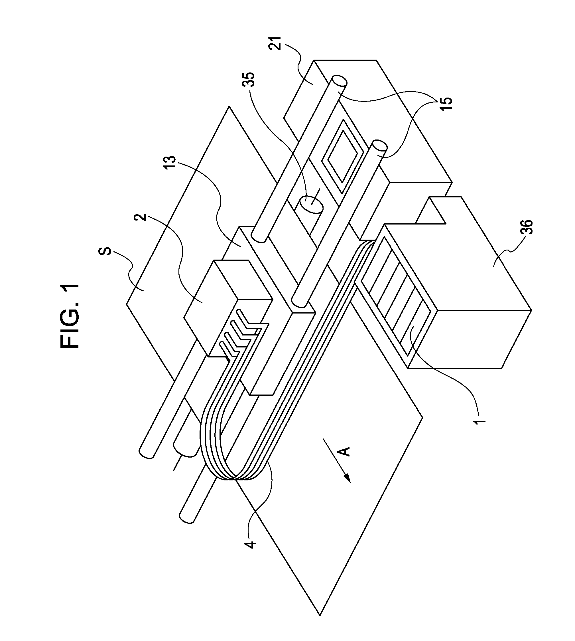
[0040]FIG. 1 is a perspective view of an inkjet recording apparatus according to a first exemplary embodiment of the present invention. The inkjet recording apparatus illustrated in FIG. 1 repeats a reciprocating movement of a recording head 2 (main scanning) and a conveyance movement of a recording medium S (e.g., plain paper, specialty paper, and transparency film) by a predetermined pitch (sub scanning). In synchronization with these movements, the inkjet recording apparatus selectively discharges ink from the recording head 2 and deposits the ink onto the recording medium S to create a letter, a symbol, and an image. The inkjet recording apparatus is of a serial type.

[0041] In FIG. 1, the recording head 2 is detachably mounted on a carriage 13. The carriage 13 is slidably supported on two guide rails 15 and is reciprocated along the guide rails 15 by a driving ...


PUM


Abstract

A recording apparatus having a diaphragm valve disposed between an ink tank and a recording head, in which closing and opening the valve produces a flow of ink. The ink tank includes two independent connection ports adjacent to one end at the bottom and a structure being configured to restrict an upward flow of ink and being located above the connection ports. Restricting the upward flow allows a small amount of ink flowing in and out to produce an entire flow of ink within the ink tank. Therefore, variations in concentration caused by precipitation of ink can be reduced.

Description

BACKGROUND OF THE INVENTION [0001] 1. Field of the Invention [0002] The present invention relates to a liquid container capable of accommodating pigment ink therein and to an inkjet recording apparatus that supplies the ink from the liquid container to a recording head via a tube or another member. [0003] 2. Description of the Related Art [0004] Inkjet printing is a printing method that forms an image by spraying a single-color ink or inks of different colors prepared for color printing onto a print medium (e.g., paper or transparency film). A recording apparatus using this inkjet printing method includes a liquid container (ink tank) as a cartridge in the vicinity of a print head on a carriage, the liquid container being integral with or separate from the print head. When the ink has run out in the liquid container, the cartridge is replaced with a new one to restock ink. This cartridge replacement type is the most popular inkjet printer type. [0005] However, the cartridge replacem...

Claims


Application Information

Patent Timeline
Patent Type & Authority Applications(United States)
IPC IPC(8): B41J2/175
CPCB41J2/17513B41J2/17509
Inventor WATANABE, SHIGERU
Owner CANON KK
Why Eureka
Eureka Blog
Learn More