Gas combusion-type impact device

a technology of impact device and gas combustion chamber, which is applied in the direction of nailing tools, manufacturing tools, stapling tools, etc., can solve the problems of not carrying out the combustion of gaseous mixture, consuming a lot of time for air/fuel to be released, and the mixing of combustible gas and air in the combustion chamber cannot be efficiently carried out, etc., to achieve quick and easy construction of nailing machines, the effect of quick ignition of gaseous mixtur

Active Publication Date: 2006-10-26
MAX CO LTD
View PDF13 Cites 4 Cited by
  • Summary
  • Abstract
  • Description
  • Claims
  • Application Information

AI Technical Summary

Benefits of technology

[0012] The vortex generator in the portion of the air current generated by the rotary fan in the combustion chamber is formed on the upstream side of the injection nozzle, and the vortexes generated near the injection nozzle in the combustion chamber by the vortex generator so that the agitation of the combustion gas injected into the combustion chamber and the air therein is promoted by the vortexes. Therefore, the agitation of the combustible gas and the air in the combustion chamber can be carried out efficiently. It also becomes possible to quickly carry out the generation of the gaseous mixture at a predetermined air / fuel ratio in the combustion chamber, and quicken the time at which the gaseous mixture can be ignited.
[0013] The retention generator is formed along the portion of the flow of the gaseous mixture generated in the combustion chamber by the rotary fan which is on the downstream side of the ignition device, and renders it easy to collect the gaseous mixture, which is generated by the rotary fan, near the ignition device. Therefore, the air / fuel ratio of the gaseous mixture which is around the ignition device attains a level at which the gaseous mixture can be ignited quickly. Since the gaseous mixture can be ignited quickly, the igniting of the gaseous mixture by a triggering operation can be done in a short period of time after the starting of the supplying of the combustible gas into the combustion chamber.
[0014] The vortex generator is formed on the upstream side of the injection nozzle, and the vortexes are generated near the injection nozzle in the combustion chamber, by which vortexes the agitation of the combustible gas, which is injected into the combustion chamber, and the air therein is promoted. The retention generator is formed on the downstream side of the ignition device, and makes it easy to collect the gaseous mixture, which is generated by the rotary fan, near the ignition device, so that the agitation of the combustible gas and air in the combustible chamber can be carried out efficiently. Moreover, the air / fuel ratio of the gaseous mixture around the ignition device quickly attains a level at which the gaseous mixture can be ignited. Therefore, the igniting of the gaseous mixture becomes able to be done more quickly.
[0015] Since the vortex generator provided on the upstream side of the injection nozzle and the retention generator provided on the downstream side of the ignition device are formed by a common vortex and retention generator in the combustion chamber, the construction of the nailing machine becomes simple, and the reduction of the cost can be attained.

Problems solved by technology

Therefore, the mixing of the combustible gas and air in the combustion chamber cannot be efficiently carried out, and it takes much time before the air / fuel ratio of the gaseous mixture in the whole region of the interior of the combustion chamber attains a level at which the condition in which the gaseous mixture can be ignited by the sparks generated by the ignition device is obtained.
As a result, when the sparks are generated from the ignition device by operating the trigger immediately after the formation of the gaseous mixture is started with the combustible gas supplied into the combustion gas, the combustion of the gaseous mixture is not carried out.
When it takes much time to form the gaseous mixture, an operation response is low, so that the operation efficiency is spoiled.

Method used


Image

  • Gas combusion-type impact device
  • Gas combusion-type impact device
  • Gas combusion-type impact device

Examples


Embodiment Construction

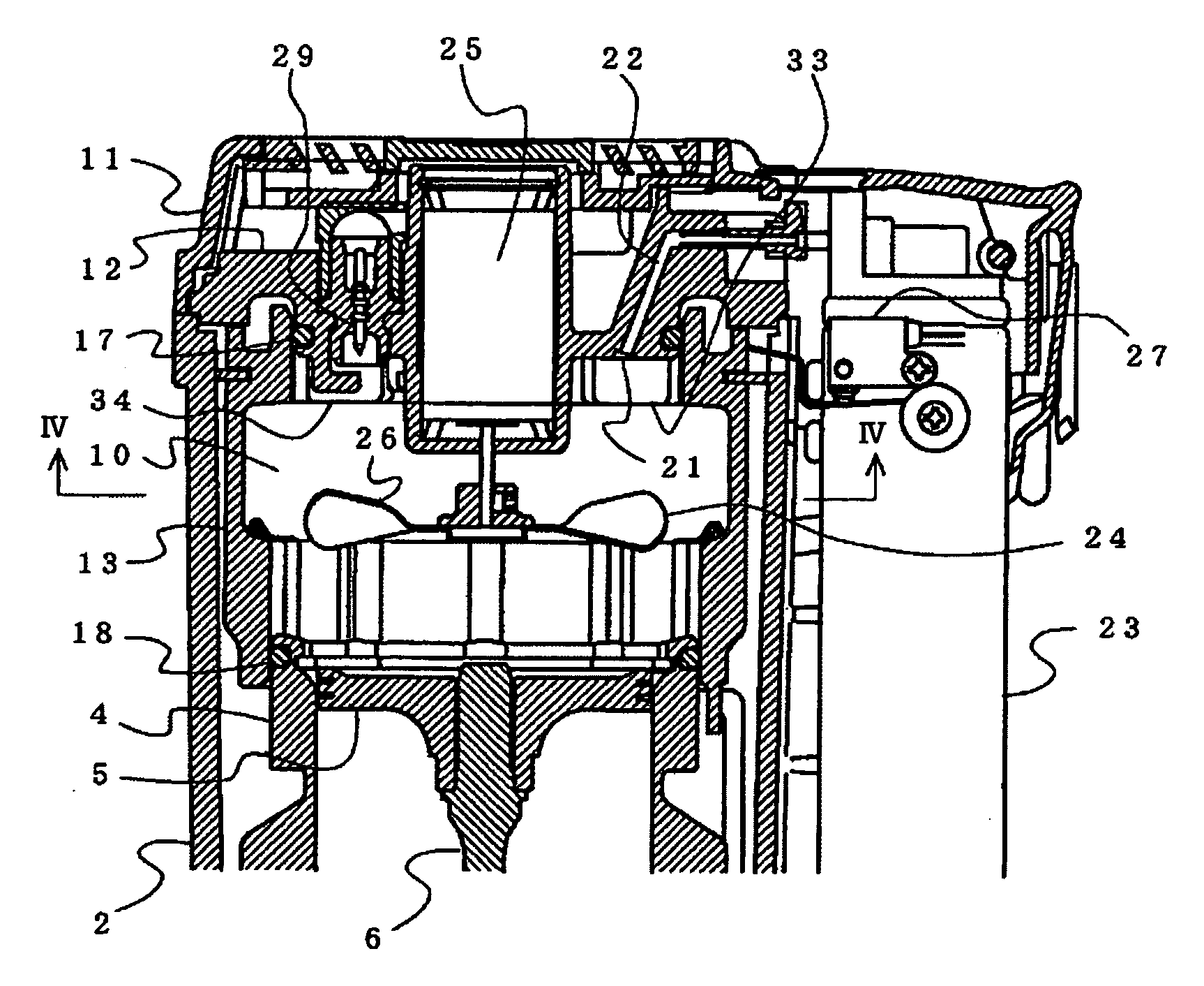
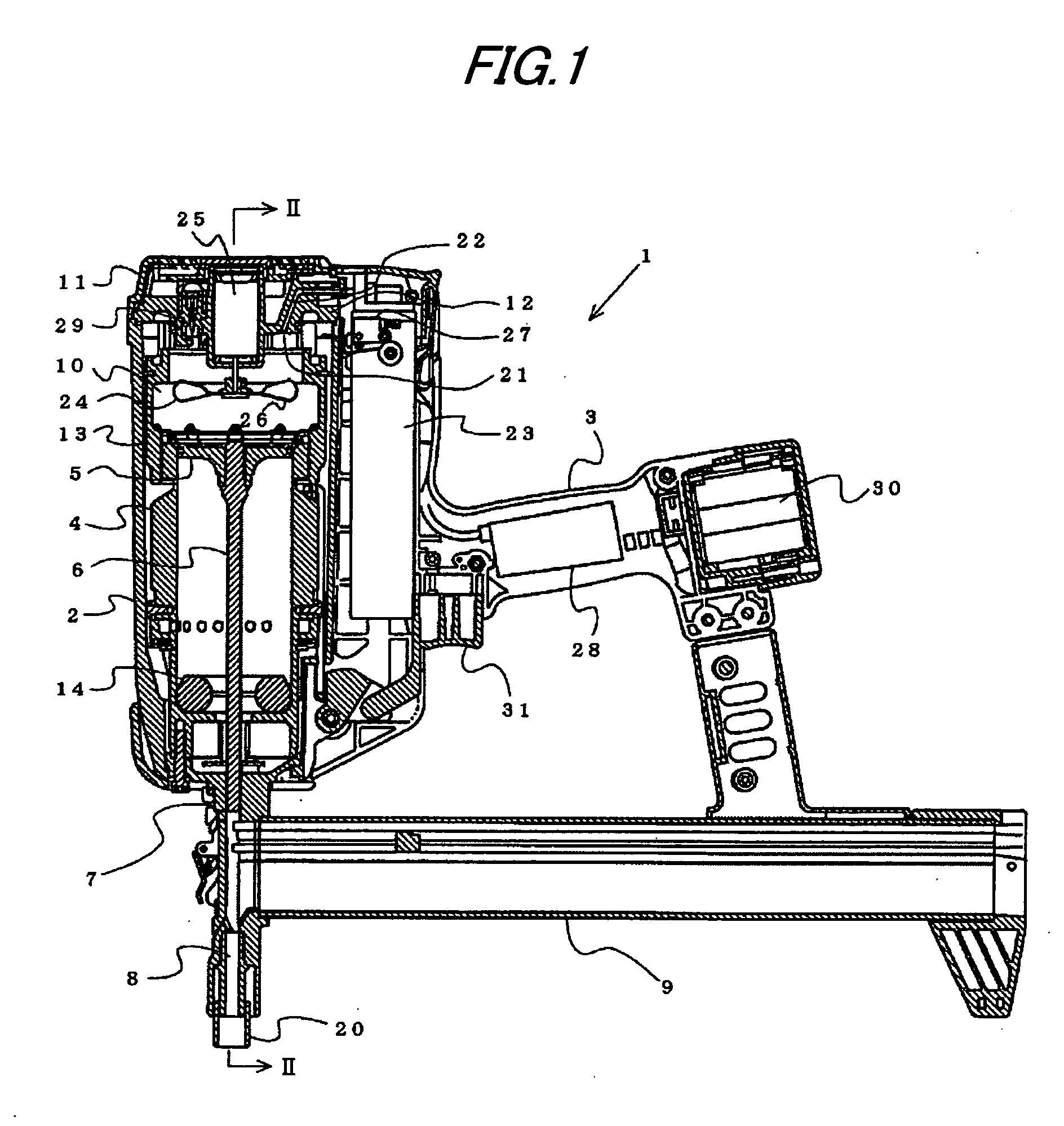
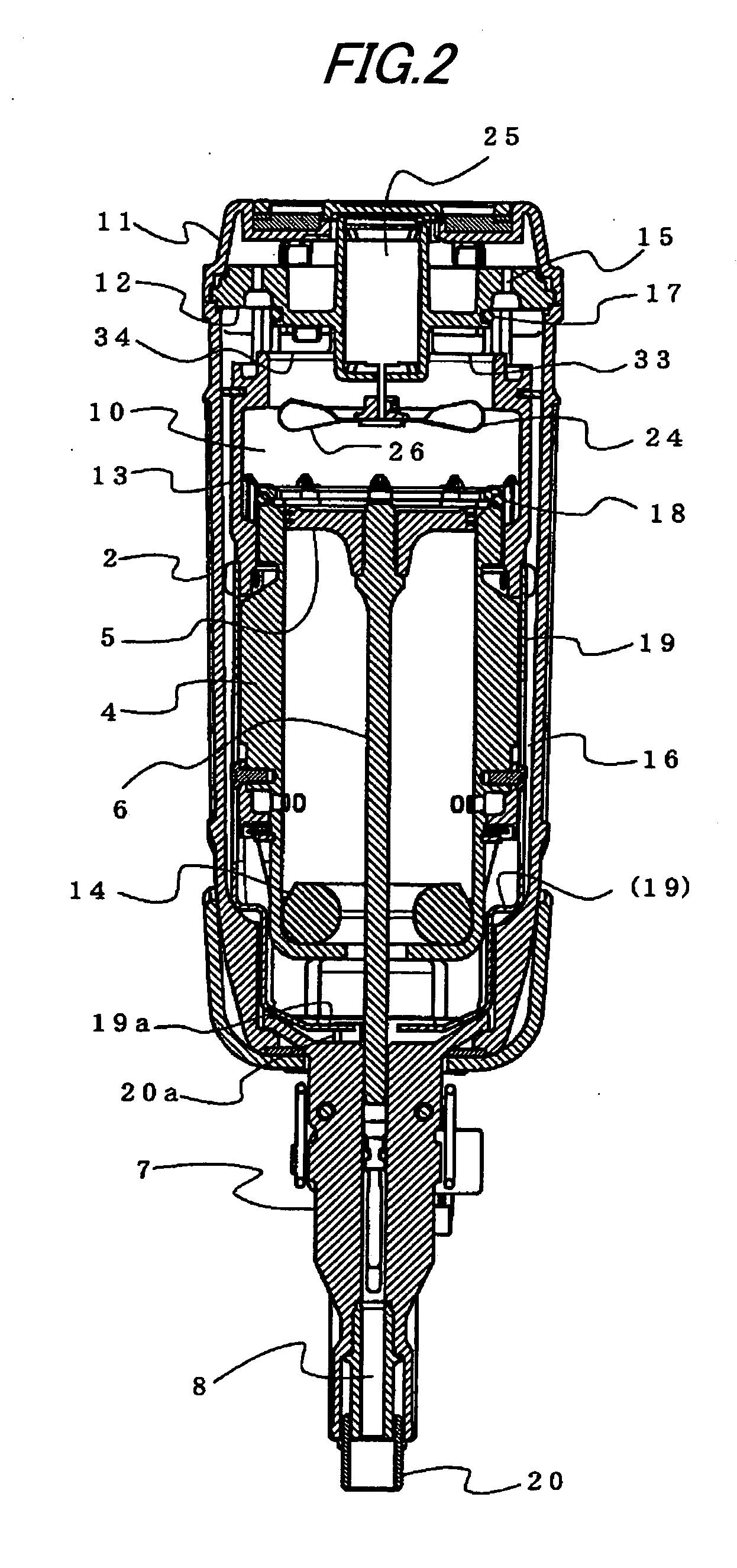
[0023]FIG. 1 shows a combustion gas driven nailing machine representing an embodiment of the gas combustion type impact tool according to the present invention. In the combustion gas driven nailing machine 1, a driving cylinder 4 is held in a housing 2 on which a rearwardly extending grip 3 is formed so as to be integral therewith as shown in FIG. 1. In this driving cylinder 4, a driving piston 5 to a lower surface of which a nail striking driver 6 is joined is slidably housed. In a lower portion of the housing 2, a nose 7 having a nail discharge port 8 adapted to guide nails to be guided toward a work is fixed. The driver 6 joined to the driving piston 5 is slidably held and guided in the nail discharge port 8 of the nose 7. On the rear side of this nose 7, a magazine 9 filled with a plurality of nails is fixed in a connected state, and the nails in the magazine 9 are supplied in order into the nail discharge port 8. The nails supplied to the interior of the nail discharge port 8 a...


PUM


Abstract

An injection nozzle 21 for injecting a combustible gas into an annular combustion chamber 10 formed above a driving cylinder 4 is formed so as to face the interior of the combustion chamber 10, is which a rotary fan 24 for mixing a combustion gas supplied into the combustion chamber 10 and air is provided. A vortex generator 33 is formed in an upstream side of the injection nozzle 21 in an air flow formed in the combustion chamber 10 by the rotary fan. Vortexes are generated near the injection nozzle 21 in the combustion chamber 10 by the vortex generator 33, so that the mixing of the combustion gas and air is promoted.

Description

TECHNICAL FIELD [0001] The present invention relates to a gas combustion type impact tool, in which a gaseous mixture are formed by mixing a combustible gas and air in a combustion chamber formed on an upper side of a driving cylinder, a driving piston held in the driving cylinder is driven by a pressure of a combustion gas generated by combusting the gaseous mixture in the combustion chamber, and a nail striking operation and the like are carried out. BACKGROUND ART [0002] As an example of the gas combustion type impact tool, a combustion gas driven nailing machine is known, which is adapted to inject a combustible gas into a sealed combustion chamber and form a gaseous mixture of the combustible gas and air therein, burn the gaseous mixture in the combustion chamber and generate a high-pressure combustion gas therein, exert the high-pressure combustion gas on a driving piston held in a driving cylinder and drive the driving piston with an impact therein, and strike a nail into a s...

Claims


Application Information

Patent Timeline
Patent Type & Authority Applications(United States)
IPC IPC(8): B25C1/14B25C1/08F01B23/06
CPCB25C1/08
Inventor TANAKA, HIROSHIOSUGA, SATOSHIYOKOCHI, YASUSHI
Owner MAX CO LTD
Why Eureka
Try Eureka