Fluid agitation method, fluid agitation system, and cartridge

a technology of fluid agitation and fluid, which is applied in the direction of rigid containers, transportation and packaging, internal fittings, etc., can solve the problems of increasing the cost of the cartridge x, the drawback of the conventional fluid agitation method, and the inability to meet the needs of the customer, so as to achieve the effect of performing more properly

Active Publication Date: 2014-11-04
ARKRAY INC
View PDF32 Cites 0 Cited by
  • Summary
  • Abstract
  • Description
  • Claims
  • Application Information

AI Technical Summary

Benefits of technology

[0007]The present invention has been proposed under the foregoing situation. An object of the present invention is to provide a technique whereby fluid agitation can be performed more properly.
[0009]The foregoing method eliminates the need to load an object for agitating the fluid in the agitation chamber, and also allows shifting a stagnation point of the swirling flow generated in the fluid. Such method allows promoting the agitation of the fluid.
[0010]Preferably, the frequency range includes a frequency at which the oscillation amplitude of the wall becomes maximum. Such arrangement causes the oscillation mode of the wall to prominently fluctuate at the frequency that makes the maximum oscillation amplitude of the wall. Therefore, the flow pattern of the swirling flow generated in the fluid can be prominently changed. This is advantageous for promoting the agitation of the fluid.
[0011]Preferably, the agitation chamber is circular, and the wall constitutes a bottom surface of the agitation chamber. Such structure is advantageous for generating the swirling flow in the fluid.
[0012]Preferably, the wall has a mass distribution uneven in a circumferential direction of the agitation chamber. Such structure allows efficiently changing the oscillation mode of the wall, which is circular.

Problems solved by technology

However, employing the agitation particle 93 that satisfies such requirements leads to an increase in cost of the cartridge X. In the case, especially, where the cartridge X is of a disposable type, the increase in cost constitutes a major obstacle to regular practical use of the cartridge.
The conventional fluid agitation method has another drawback.
Such failure leads to compromise in agitating force, thereby prolonging the time required for the specimen analysis.

Method used


Image

  • Fluid agitation method, fluid agitation system, and cartridge
  • Fluid agitation method, fluid agitation system, and cartridge
  • Fluid agitation method, fluid agitation system, and cartridge

Examples


Embodiment Construction

[0039]Preferred embodiments of the present invention will be described below with reference to the accompanying drawings.

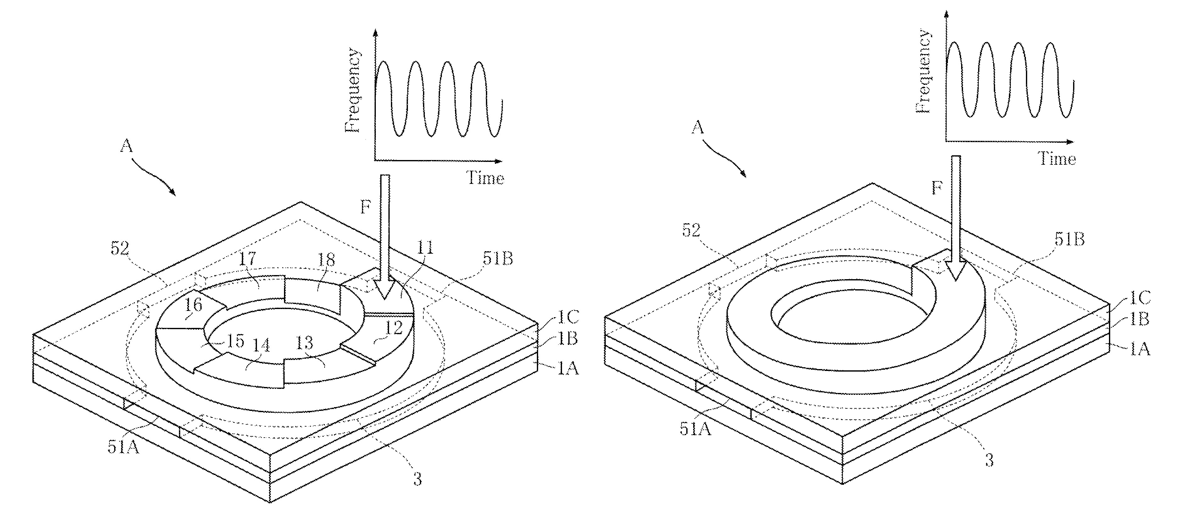
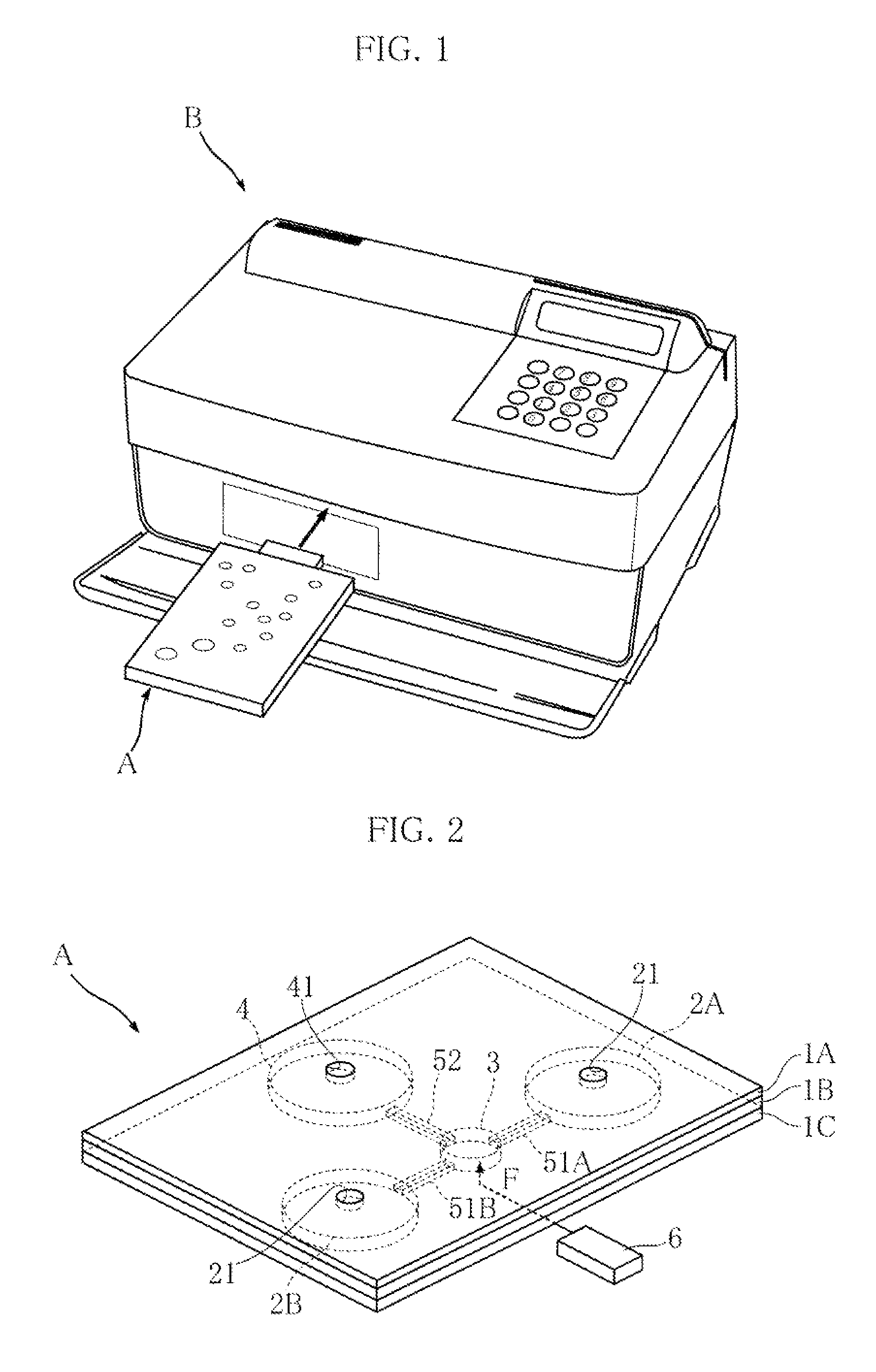
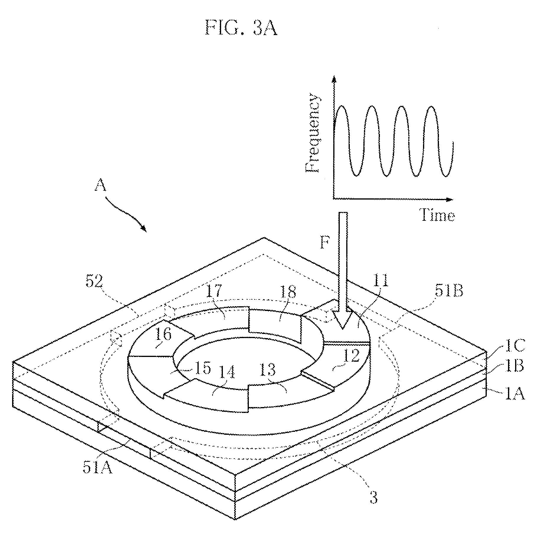
[0040]FIG. 1 depicts a specimen analysis system that employs a fluid agitation method according to the present invention. The specimen analysis system includes a cartridge A and a specimen analysis apparatus B. The cartridge A can be removably loaded in the specimen analysis apparatus B. To perform the specimen analysis, the cartridge A is spotted with the specimen, and loaded in the specimen analysis apparatus B. Then a predetermined agitation process (subsequently described) is performed with respect to the specimen in the cartridge A, which is followed by analysis of the specimen by the specimen analysis apparatus B. The specimen analysis apparatus B executes, for example by an optical technique, various measurement of specific components contained in the specimen. For example, in the case where the specimen is blood, measurement of blood cells (leukocyte, eryt...


PUM

PropertyMeasurementUnit
central angleaaaaaaaaaa
diameteraaaaaaaaaa
diameteraaaaaaaaaa

Abstract

A fluid agitation method is provided, whereby a swirling flow is generated in a trace amount of fluid, thereby agitating the fluid. The fluid agitation method includes introducing the fluid into an agitation chamber (3) including a wall having an uneven mass distribution, and applying oscillation (F) to the wall with frequencies varying in a predetermined frequency range. The uneven mass distribution of the wall is attained, for example, by arranging a plurality of thickened portions (11 to 18) of different thicknesses in a ring.

Description

TECHNICAL FIELD[0001]The present invention relates to a fluid agitation method and a fluid agitation system. The present invention also relates to a cartridge to be used in the fluid agitation system.BACKGROUND ART[0002]Health conditions can be checked by analyzing, for example, a specific component in the blood. Recently, analysis apparatuses of a relatively compact size have been developed for executing the component analysis. Some of the analysis apparatuses have a fluid agitation function of mixing the blood and a diluting fluid or mixing the diluted blood and a reagent, for performing the component analysis.[0003]FIG. 18 depicts a cartridge X and an agitation arm 96 employed in a conventional fluid agitation method (see patent document 1 cited below). A main body 91 of the cartridge X includes a dilution chamber 92 for diluting blood 94 therein. The blood 94 introduced into the dilution chamber 92 is agitated with a diluting fluid 95. For performing the agitation, agitation par...

Claims


Application Information

Patent Timeline
Patent Type & Authority Patents(United States)
IPC IPC(8): B01F11/02B01F11/00G01N33/49
CPCB01F11/0266G01N33/49B01F31/86
Inventor KOTERA, HIDETOSHISUZUKI, TAKAAKIKANDA, KENSUKENODA, YUICHIRO
Owner ARKRAY INC
Why Eureka
Try Eureka