Eureka AIR delivers breakthrough ideas for toughest innovation challenges, trusted by R&D personnel around the world.

Driving apparatus

a technology of driving apparatus and motor, which is applied in the direction of machines/engines, instruments, television systems, etc., can solve the problems of difficult tuning of derivative control and inability to properly improve response, so as to achieve the effect of properly improving the response of the sma actuator

Inactive Publication Date: 2007-05-17
KONICA MINOLTA INC
View PDF4 Cites 99 Cited by
  • Summary
  • Abstract
  • Description
  • Claims
  • Application Information

AI Technical Summary

Benefits of technology

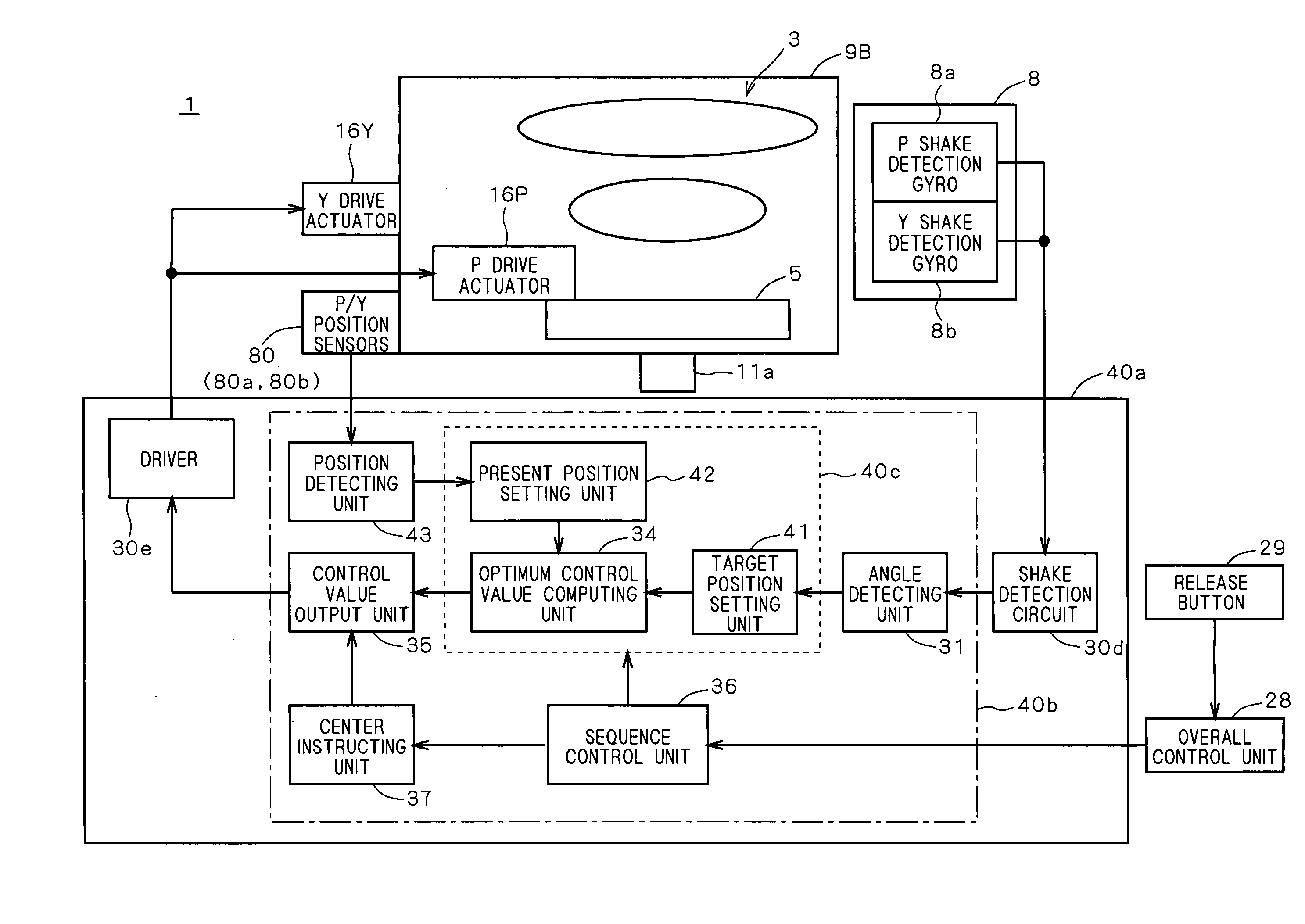
[0009] The present invention is directed to a driving apparatus. According to the present invention, the driving apparatus includes: (a) a movable part; and (b) an actuator connected to the movable part and driving the movable part, the actuator having a first elastic part and a second elastic part which are connected to the movable part in a push-pull relation. At least one of the first elastic part and the second elastic part is formed as a wire made of a shape memory alloy, and a sectional shape of the wire is flattened in shape. With the configuration, heat dissipation of shape memory alloy (SMA) increases, so that the response of the SMA actuator can be properly improved.
[0010] In a preferred embodiment of the invention, the driving apparatus further includes: (c) a sensor for obtaining a measurement value with regard to a driving of the movable part; and (d) a controller for passing current to the wire on basis of a deviation between a drive target value of the movable part and the measurement value in order to control a driving of the movable part. With the configuration, servo driving on the movable part can be performed properly.

Problems solved by technology

Since tuning of the derivative control is difficult, there is also a problem such that a correction according to a change in environment temperature and the like is necessary.
In the case of improving the response of the SMA actuator only by improving the control system (software), various problems occur as side effects.
As a result, the response cannot be properly improved.

Method used


Image

  • Driving apparatus
  • Driving apparatus
  • Driving apparatus

Examples


Embodiment Construction

Configuration of Main Part of Cellular Phone

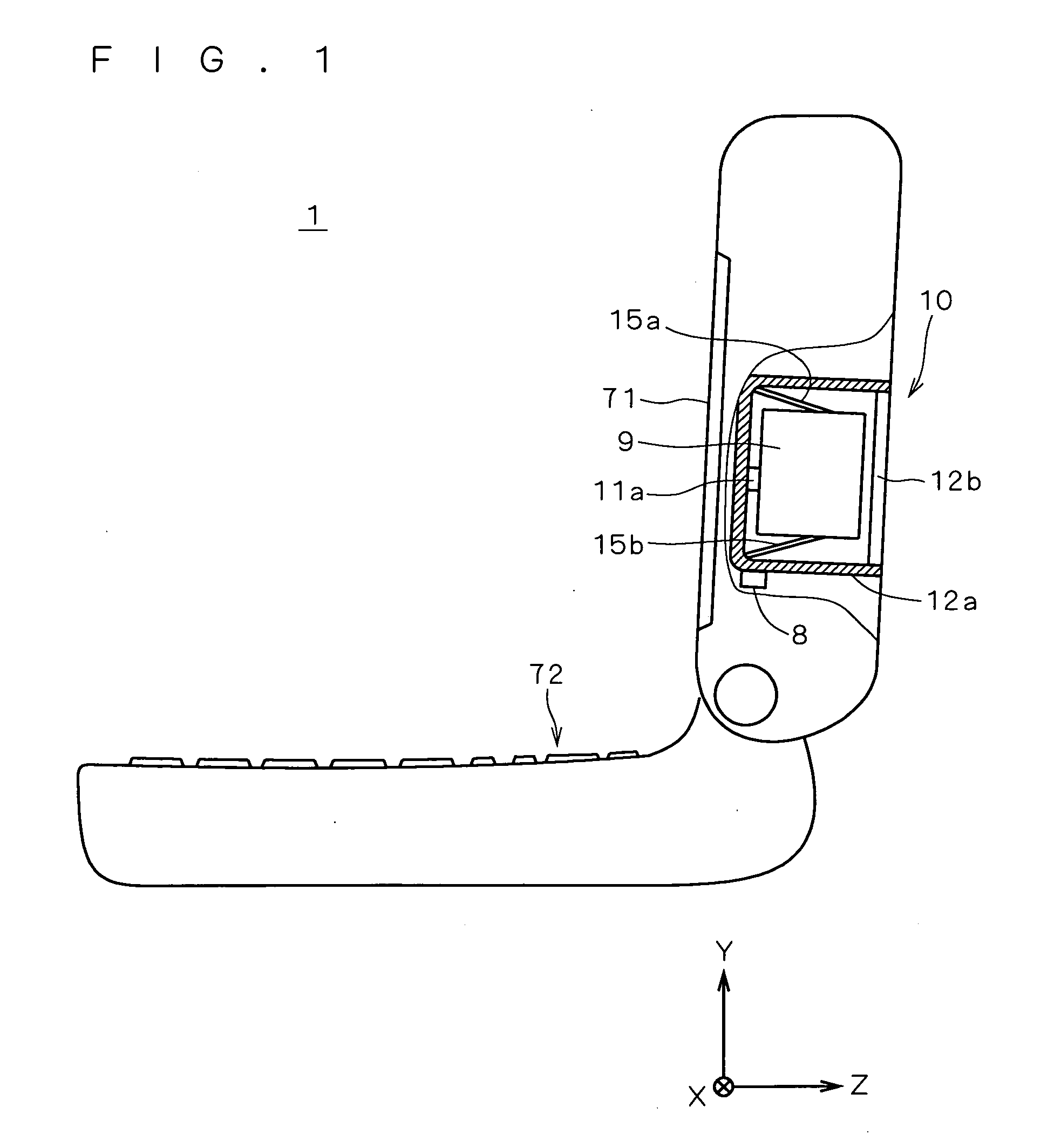
[0033]FIG. 1 is a side view of a cellular phone 1 in which an auto image stabilization system 10 is assembled. The cellular phone 1 has a communication function and also an image capturing function, and functions not only as a communication device but also as an image capturing device.

[0034] As shown in FIG. 1, the cellular phone 1 has the auto image stabilization system 10 having a configuration simpler than that of an auto image stabilization system 10A which will be described later and also has, on the surface of the body, a display 71 such as an LCD (Liquid Crystal Display) and an input part 72 constructed by various keys. In a broken-out part in FIG. 1, the internal state of the cellular phone 1 is shown. As shown in the broken-out part, the cellular phone 1 has therein the auto image stabilization system 10 functioning as a driving apparatus.

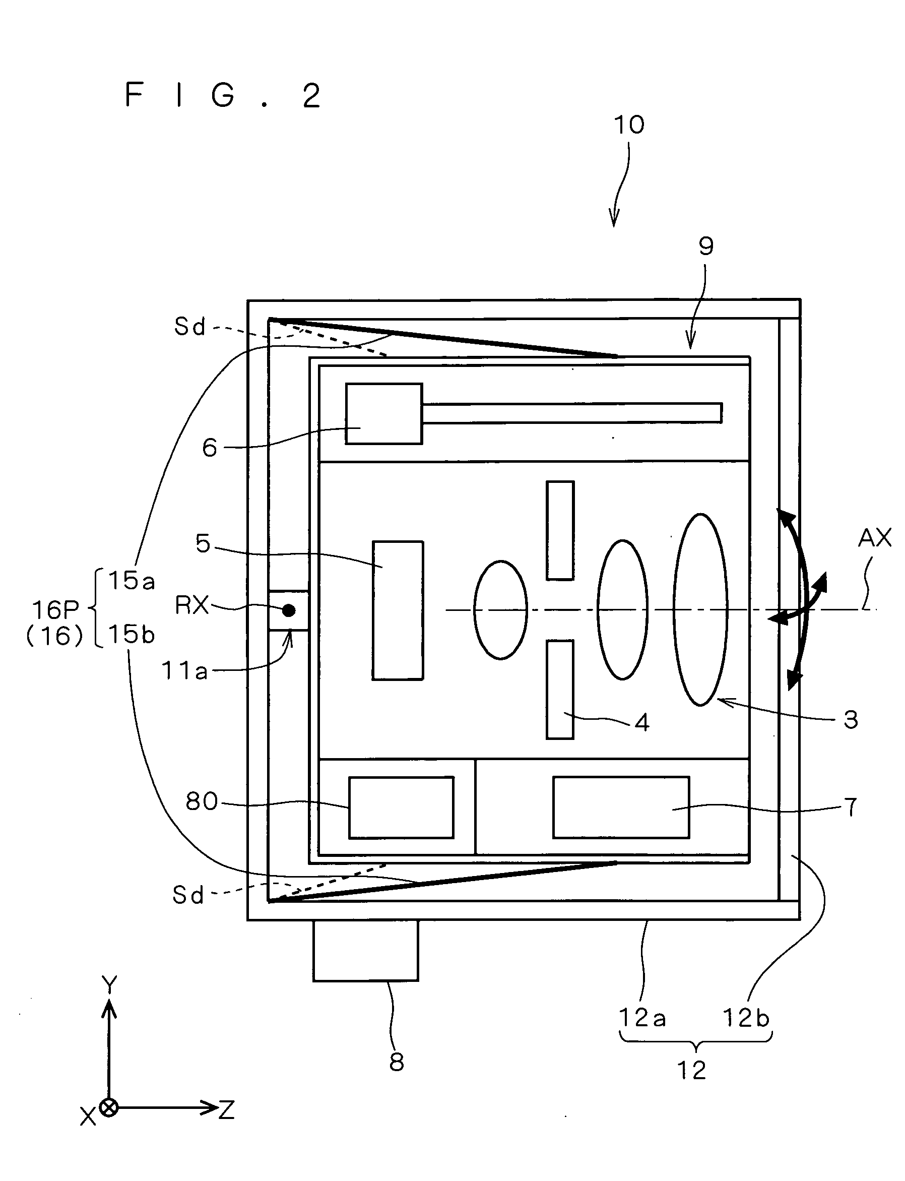
[0035]FIG. 2 is a diagram more specifically showing elements included in the auto image s...


PUM


Abstract

In an auto image stabilization system, a driving member formed as a wire of shape memory alloy (SMA) is retained by a projection of an image capturing unit. A distance Lb from the rotation center of an elastic deforming part to center of gravity (point of application) of the image capturing unit is longer than a distance La from the rotation center of the elastic deforming part to the projection (power point). In the configuration, equivalent mass (apparent mass) of the image capturing unit becomes (Lb / La) times, and it causes deterioration in response. Consequently, the driving member having an ellipse-shaped section in which a value obtained by dividing the width in the longer direction of the section by the width in the shorter direction is 1.3 or larger is employed. As a result, heat dissipation of the driving member increases, so that response in the SMA actuator can be properly improved.

Description

[0001] This application is based on application No. 2005-331598 filed in Japan, the contents of which are hereby incorporated by reference. BACKGROUND OF THE INVENTION [0002] 1. Field of the Invention [0003] The present invention relates to a driving apparatus for driving a movable part by using an actuator connected to the movable part. [0004] 2. Description of the Background Art [0005] A shape memory alloy (hereinbelow, also called “SMA”) has a property such that even if it is plastic-deformed by an external force at a temperature equal to or less than martensite transformation start temperature, when heated to a temperature equal to or higher than reverse transformation end temperature, the SMA regains its memorized original shape. A driving apparatus using, as an actuator, an SMA having such a property is known. [0006] In the case of making auto image stabilization by an actuator using the SMA (hereinbelow, also called “SMA actuator”), the driving performance of cancelling out a...

Claims


Application Information

Patent Timeline
IPC IPC(8): H04N5/225H04N5/228
CPCH04N5/2251H04N5/23248H04N5/23258H04N5/23287G03B2205/0076G03B2205/0023H04N23/50H04N23/60H04N23/68H04N23/6812H04N23/687
Inventor HARA, YOSHIHIRO
Owner KONICA MINOLTA INC
Why Eureka
Eureka Blog
Learn More