Method and Apparatus for Measuring Fluid Properties

a technology of fluid properties and methods, applied in the field of methods and apparatus for measuring fluid properties, can solve problems such as poor resolution of systems

Inactive Publication Date: 2006-01-19
SCHLUMBERGER TECH CORP
View PDF4 Cites 98 Cited by
  • Summary
  • Abstract
  • Description
  • Claims
  • Application Information

AI Technical Summary

Benefits of technology

[0013] The amount and rate of thermal energy exchange is dependent on the nature of the fluid, so that properties of the fluid can be determined from a measurement of the exchange. Measuring the temperature response of the heat exchange element is a simple and convenient way of obtaining an indication of the energy exchange, and can be performed particularly accurately by using a temperature sensor positioned centrally inside the heat exchange element. In this location, the sensor detects the maximum bulk temperature changes in the heat exchange element so that minor regional fluctuations are avoided. Also, the sensor is isolated from the fluid, and hence from any cooling or heating effect produced thereby on the sensor which could distort the measurements and reduce the magnitude of any detected temperature changes, giving a system with poor resolution.
[0018] The method may further comprise arranging a second temperature sensor offset from said temperature sensor, the second temperature sensor being operable to measure the temperature of the heat exchange element; measuring the temperature of the heat exchange element during the exchange of thermal energy, using the second temperature sensor; and using the temperature measurement from the second temperature sensor when determining the one or more properties of the fluid. The additional information available from the second temperature sensor can be used to improve accuracy, since errors and fluctuations in the measurements made with the first sensor that are not caused by the fluid can be identified and accounted for. The second temperature sensor may be arranged inside the heat exchange element, or outside the heat exchange element. A particularly convenient technique for providing the two sensors is such that they comprise respectively first and second portions of an optical fiber of an optical fiber temperature sensor. Thus, a single temperature sensing system can be used to implement both sensors, allowing both sensors to be interrogated in a single operation. While the two sensors may be discrete sensors coupled to a single optical fiber, an advantageous arrangement is if the optical fiber temperature sensor is a distributed temperature sensing system. Different sections of the measured distributed temperature profile will correspond to the two sensors. In either case, the optical fiber temperature sensor may be a double-ended optical fiber temperature sensor system. This allows the sensors to be interrogated from either end of the system, giving additional information that can be used to enhance accuracy, such as by averaging of the measurements.

Problems solved by technology

Also, the sensor is isolated from the fluid, and hence from any cooling or heating effect produced thereby on the sensor which could distort the measurements and reduce the magnitude of any detected temperature changes, giving a system with poor resolution.

Method used


Image

  • Method and Apparatus for Measuring Fluid Properties
  • Method and Apparatus for Measuring Fluid Properties
  • Method and Apparatus for Measuring Fluid Properties

Examples


Embodiment Construction

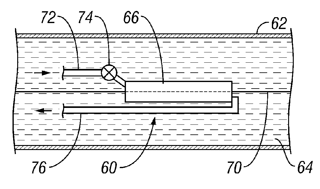
[0035] The present invention uses optical fiber or other temperature sensors to measure temperature. It further makes use of the physical principle underlying the hot wire anemometer described above in the introduction, whereby the temperature change of an object in flowing fluid can be used to calculate the rate of flow, because the heat energy transferred between the object and the fluid is proportional to the flow rate. However, this principle is taken further in that the heat energy transfer also depends on other properties of the fluid, such as the fluid type, so that proportions of various constituents in the fluid can be determined. The fluid need not be flowing. According to embodiments of the invention, a heat exchanger is disposed in thermal contact with a fluid of interest, and either heated above or cooled below the temperature of the fluid. This creates a temperature difference so that the fluid exchanges heat with the heat exchanger and the heat exchanger undergoes a c...


PUM


Abstract

A method of measuring fluid properties such as flow velocity, flow rate, and fluid composition comprises positioning a heat exchange element with a temperature sensor, such as an optical fiber temperature sensor, arranged centrally inside the element in thermal contact with a fluid of interest, heating or cooling the heat exchange element to cause a temperature difference and exchange of thermal energy between the element and the fluid, using the temperature sensor to measure the temperature of the heat exchange element during the exchange of thermal energy, and determining properties of the fluid from the temperature measurement. A second temperature sensor can be provided offset from the first sensor to provide additional measurements to improve accuracy, and a plurality of heat exchange elements with temperature sensors can be used together to determine fluid properties over a large region.

Description

BACKGROUND OF THE INVENTION [0001] 1. Field of the Invention [0002] The present invention relates to a method and apparatus for measuring properties of fluids, particularly, but not exclusively, fluids within oil wells, the properties including fluid flow and fluid composition. [0003] 2. Description of Related Art [0004] A known device for measuring fluid flow is the hot wire anemometer described in L. V. King, “Precision measurement of air velocity by means of the linear not-wire anemometer”, Phil. Mag., Series 6,29, p. 599-604 (1915), the operating principle of which depends on the cooling effect of a fluid flowing past a heated object, so that a measurement of the temperature change of the object gives an indication of the rate of flow of the fluid. A thin wire, typically a few millimeters long, is placed orthogonally to the direction of the flow to be measured. A voltage is applied across the wire, and the resulting current flow through the wire, which is inversely proportional ...

Claims


Application Information

Patent Timeline
Patent Type & Authority Applications(United States)
IPC IPC(8): G01F1/68E21B47/10
CPCG01F1/68E21B47/1005E21B47/103G01N25/00
Inventor BROWN, GEORGE A.
Owner SCHLUMBERGER TECH CORP
Why Eureka
Try Eureka