Stent-valves for valve replacement and associated methods and systems for surgery

a valve replacement and valve valve technology, applied in the field of stent valves, can solve the problems of increasing the risks, death, and limits of patients' activities, and achieve the effect of facilitating a surgical approach and reducing risks

Inactive Publication Date: 2009-07-02
JENAVALVE TECH INC
View PDF104 Cites 377 Cited by
  • Summary
  • Abstract
  • Description
  • Claims
  • Application Information

AI Technical Summary

Benefits of technology

[0008]Some embodiments of the present invention are directed to systems, methods, and devices for cardiac valve replacement. For example, these methods, systems, and devices may be applicable to the full range of cardiac-valve therapies including the replacement of failed aortic, mitral, tricuspid, and pulmonary valves. In some embodiments, the present invention may facilitate a surgical approach whereby surgery is performed on a beating heart without the need for an open-chest cavity and heart-lung bypass. This minimally-invasive surgical approach may reduce the risks associated with replacing a failed native valve in the first instance, as well as the risks associated with secondary or subsequent surgeries to replace failed artificial (e.g., biological or synthetic) valves.
[0011]Alternatively or additionally, in some embodiments the third section of the stent component may include at least one attachment element. Each attachment element of the stent-valve may include, for example, a geometrical opening (e.g., circular or ovular), hook, or strap configured for removable attachment to a complimentary structure of a delivery device. In addition, each attachment element may correspond to all or a portion of a commissural post, to which a commissure between two valve leaflets may be attached. The attachment element(s) may allow the stent-valve to be partially expanded within a patient's body while the stent-valve remains attached to the delivery device. This may allow the stent-valve to be returned to a collapsed configuration and repositioned within the patient's body when it is determined that fully expanding the stent-valve would cause the stent-valve to be installed incorrectly. Alternatively or additionally, this may allow the stent-valve to be returned to the collapsed configuration and removed from the patient's body when it is determined that the stent-valve is not functioning properly (e.g., not permitting sufficient flow). In some embodiments, the stent-valve may include one attachment element. In other embodiments, the stent-valve may include at least two, three, six, or any other suitable number of attachment elements. In some embodiments, the fully-expanded stent diameter in the region of the attachment element(s) may be smaller than the diameter of the region that houses an associated valve. This may reduce the risk of injury to the patient's body (e.g., perforation of the aorta) from the attachment elements and / or make it easier to affix the attachment elements to the complimentary structure of the delivery device.
[0012]In some embodiments, the stent component of the stent-valve may include a lattice structure with a plurality of cells. The lattice structure may be formed from, for example, a shape-memory alloy such as nitinol or any other suitable material(s). The cells in the lattice structure may be most densely populated in the section of the stent component that includes the fixation element. This may provide added support to the fixation element and increase the stability of the stent-valve. In some embodiments, the lattice structure may form at least one elongate stem (e.g., commissural post) that extends distally along the stent component towards the at least one attachment element. The at least one stem may connect directly to the at least one attachment element. Alternatively, the lattice structure may form at least one supporting element for connecting the at least one stem to the at least one attachment element. In some embodiments, all of the cells in the lattice structure may be closed cells, which may facilitate recapture of the stent-valve from the partially-expanded configuration to the collapsed configuration.
[0028]In some embodiments, the top portion of the occluder may include a first material and the bottom portion of the occluder may include a second material, where the second material may be coarser than the first material. This may facilitate the formation of scar tissue on the outer portion and speed the heeling process. For example, the first and / or second materials may include felt(s) and / or velour(s) made from Teflon, Dacron, polyurethane, polydioxanone, polyhydroxybutyrate, and / or other material.

Problems solved by technology

However, tissue adherences resulting from the first surgery may increase the risks (e.g., death) associated with subsequent valve replacement surgeries.
Such anti-coagulant treatment significantly limits patients' activities and can cause various other complications.
Biological valves do not require such anti-coagulation treatment but typically fail within 10-15 years.
These PHVT attempts have various shortcomings, including their inability to ensure proper positioning and stability of the replacement valve within the patient's body.
Conventional closure devices for closing access orifices are also lacking in several respects, including the looseness of their fit which can cause bleeding after surgery.
These closure devices also lack a central lumen, which renders them incompatible with guide wire delivery systems.

Method used


Image

  • Stent-valves for valve replacement and associated methods and systems for surgery
  • Stent-valves for valve replacement and associated methods and systems for surgery
  • Stent-valves for valve replacement and associated methods and systems for surgery

Examples


Embodiment Construction

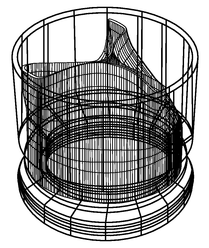
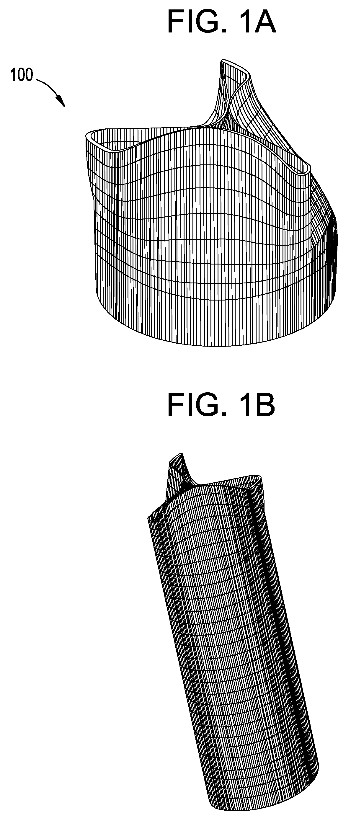
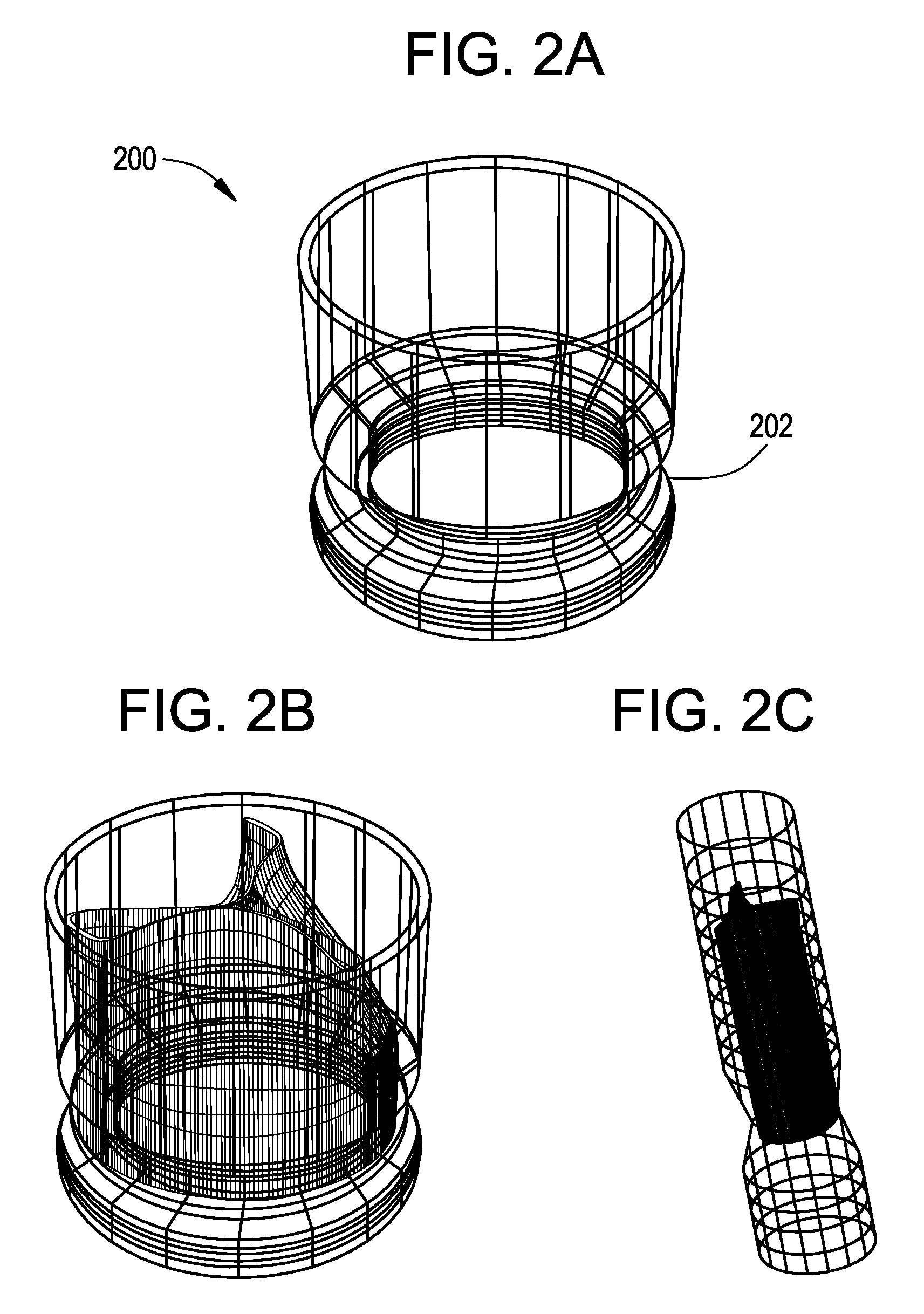
[0061]FIGS. 1A-3B show components 100, 200, and 300 for use in replacing, for example, a failed (e.g., degenerated) aortic valve, mitral valve, or pulmonary cardiac valve (e.g., in a pediatric patient) in accordance with some embodiments of the present invention. More particularly, FIGS. 1A and 1B show a valve component 100. FIGS. 2A-2C show a stent component 200 for housing valve component 100. FIGS. 3A and 3B show a stent component 300 for housing stent component 200 and valve component 100. A device that includes components 100 and 200 may be referred to as a single-stent-valve. A device that additionally includes component 300 may be referred to as a double-stent-valve.

[0062]FIG. 4 shows a double-stent-valve 400 that includes valve component 100, stent component 200, and stent component 300 in accordance with some embodiments of the present invention. Double-stent-valve 400 may replace a failed native or artificial valve. As used herein, a “native valve” refers to a valve natura...


PUM


Abstract

Stent-valves (e.g., single-stent-valves and double-stent-valves), associated methods and systems for their delivery via minimally-invasive surgery, and guide-wire compatible closure devices for sealing access orifices are provided.

Description

CROSS-REFERENCE TO RELATED APPLICATIONS[0001]The present application claims the benefit of U.S. Provisional Patent Application Nos. 60 / 753,071, filed Dec. 22, 2005, 60 / 755,590, filed Dec. 29, 2005, and 60 / 843,181, filed Sep. 7, 2006, each of which is incorporated by reference herein in its entirety.FIELD OF THE INVENTION[0002]Embodiments of the present invention relate to stent-valves, associated methods and systems for their delivery via minimally-invasive surgery, and guide-wire compatible closure devices for sealing access orifices.BACKGROUND OF THE INVENTION[0003]Conventional approaches for cardiac valve replacement require the cutting of a relatively large opening in the patient's sternum (“sternotomy”) or thoracic cavity (“thoracotomy”) in order to allow the surgeon to access the patient's heart. Additionally, these approaches require arrest of the patient's heart and a cardiopulmonary bypass (i.e., use of a heart-lung bypass machine to oxygenate and circulate the patient's bl...

Claims


Application Information

Patent Timeline
Patent Type & Authority Applications(United States)
IPC IPC(8): A61F2/06
CPCA61F2/2418A61F2/243A61F2/2433A61F2/2436A61F2/2472A61F2230/0078A61F2220/0016A61F2220/0075A61F2220/0083A61F2230/0013A61F2230/0067A61F2250/006A61F2/90A61F2/966A61F2002/9511A61F2210/0042A61F2250/001A61F2250/0039A61F2002/9505A61F2002/9665A61F2210/0014A61F2/9522A61B17/12031A61B17/12131A61B2017/00606A61B2017/00623A61B2017/12095A61B17/0057A61M39/22A61F2/82A61F2/2427A61F2002/9534A61F2220/0033A61F2230/001
Inventor VON SEGESSER, LUDWIG K.DELALOYE, STEPHANE
Owner JENAVALVE TECH INC
Why Eureka
Try Eureka