Liquid ejecting apparatus

a liquid ejecting apparatus and liquid technology, applied in printing and other directions, can solve the problems of increased concentration of liquid, uneven liquid ejecting, adverse effects, etc., and achieve the effect of miniaturizing the liquid ejecting apparatus, reducing the volume of the decompression pump, and increasing the amount of air which the decompression pump discharges

Active Publication Date: 2012-02-23
SEIKO EPSON CORP
View PDF5 Cites 3 Cited by
  • Summary
  • Abstract
  • Description
  • Claims
  • Application Information

AI Technical Summary

Benefits of technology

[0014]Since the negative pressure is generated due to the fact that the decompression pump sucks out the air, the decompression pump necessarily discharges the air if the negative pressure is generated. In addition, as the number of the liquid-feeding pumps or the circulation pumps which are operated is increased, the amount of the air which the decompression pump discharges is also increased. Therefore, without operating all of the liquid-feeding pumps and the circulation pumps by the nega

Problems solved by technology

When the liquid is supplied to the ejection nozzle in the above state, unevenness in the concentration of the liquid ejected occurs, or the concentration of the liquid is increased.
Therefore, adverse effects such as a blockage of a pathway due to th

Method used


Image

  • Liquid ejecting apparatus
  • Liquid ejecting apparatus
  • Liquid ejecting apparatus

Examples


first modification

C-1. First Modification

[0058]In the above-described embodiment, the agitation operation of the ink in the ink cartridge 40 is performed when the ink of any color is ejected from the ejection head 20. However, before the ink is ejected, in the state where the ink is not ejected, at the short interval, the circulation pump 90 may be driven by using the decompression pump 130.

[0059]As described above, in the ink jet printer 10 of the embodiment, in the state where the ink is not ejected, the unneeded ink is not supplied to the ejection nozzle by the liquid-feeding pump 110 even though the decompression pump 130 is driven (refer to FIG. 5). Thereby, in the state where the ink is not ejected, at the short interval, through driving the circulation pump 90 by using the decompression pump 130, it is possible to start the printing while previously agitating the ink in the ink cartridge 40 before ejecting the ink. Therefore, for example, the printing is not performed for an extremely long tim...

second modification

C-2. Second Modification

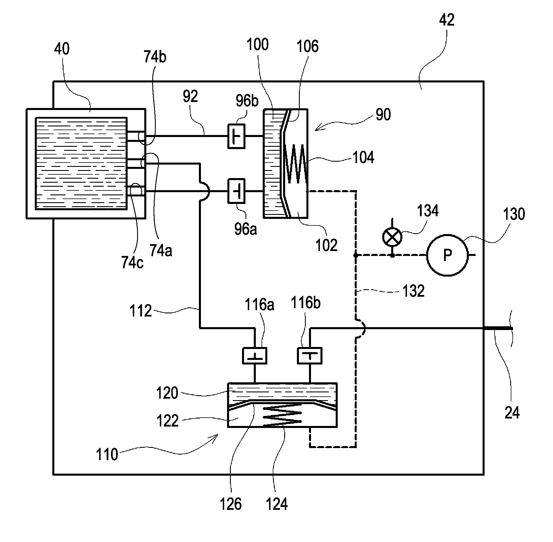
[0060]In the above-described embodiment and the first modification, the liquid-feeding pump 110 and the circulation pump 90 are driven by depressurizing the air chambers (the air chambers 122 and 102) of the inner portions of the pumps through the use of the decompression pump 130. However, the liquid-feeding pump 110 and the circulation pump 90 may be driven as follows.

[0061]FIG. 8 is an explanatory view showing a driving mechanism of the liquid-feeding pump 110 and the circulation pump 90 of the second modification. The driving mechanism of the liquid-feeding pump 110 and the circulation pump 90 of the second modification is different to the above-described driving mechanism of FIG. 5 as follows. That is, the decompression pathway 132, which introduces the negative pressure generated in the decompression pump 130, is connected to the air chamber 122 of the liquid-feeding pump 110. However, the decompression pathway 132 is not connected to the air chamber 10...


PUM


Abstract

A liquid-feeding pump that feeds liquid, which is sucked out from a liquid container, into an ejection nozzle is provided. In addition, a circulation pump that discharges the liquid, which is sucked out from the liquid container, to the liquid container is provided. Moreover, a decompression pump, which generates a pressure for operating the liquid-feeding pump, is used as a drive source of the circulation pump. Therefore, a driving mechanism for the circulation pump need not be additionally provided. Accordingly, it is possible to simplify a configuration of a liquid ejecting apparatus while being capable of agitating the inner portion of the liquid container by using the circulation pump.

Description

BACKGROUND[0001]1. Technical Field[0002]The present invention relates to a liquid ejecting apparatus that ejects a liquid from an ejection head.[0003]2. Related Art[0004]In a so-called ink jet printer, it is possible to print a high quality image by ejecting a correct amount of ink to correct positions from fine ejection nozzles. In addition, by using the technology, when ejecting various liquids instead of the ink toward a substrate, electrodes, sensors, bio-chips, or the like can also be manufactured.[0005]The liquid ejected from the ejection nozzles is supplied from a liquid container (for example, an ink cartridge) which stores the liquid. In addition, as a liquid which is stored in the liquid container, the liquid including pigment or the like, for example, a component (a component having a sedimentation property) having greater specific weight than that of solvent, is used. Moreover, in the liquid (the liquid having the sedimentation property), a solute in the liquid is sedime...

Claims


Application Information

Patent Timeline
IPC IPC(8): B41J2/175
CPCB41J2/175B41J2/17596B41J2/1752B41J2/17513
Inventor KOIZUMI, YOSHIHIRO
Owner SEIKO EPSON CORP
Why Eureka
Try Eureka