Developing apparatus and image forming apparatus

a technology of developing apparatus and image forming apparatus, which is applied in the direction of electrographic process apparatus, instruments, optics, etc., can solve the problems of reducing density, uneven toner density in part, and affecting the development effect of developer, so as to suppress deviation and effectively agitate the developer

Active Publication Date: 2015-05-07
CANON KK
View PDF4 Cites 2 Cited by
  • Summary
  • Abstract
  • Description
  • Claims
  • Application Information

AI Technical Summary

Benefits of technology

[0021]It is desirable to prevent developer leakage and a developer overflowing while keeping an effective agitation of the developer and suppressing a deviation in the developer bearing surface in the collecting chamber.

Problems solved by technology

However, when the developer is used for a long time, the developer collected from a developing sleeve into the developing apparatus is not sufficiently mixed with the developer already in the developing apparatus during the developing operation, so that the toner density is unevenly distributed in part.
Then, the collected developer is supplied to the developing sleeve again, and as a result there causes a problem in that the density is lowered.
However, even in a case where such a developing apparatus is used, when a lot of toner is consumed such as a case where an image is printed at a high rate, there still remains the problem in that the uneven toner density is partially generated or the density is decreased.
Then, the developer fallen on an inner side of the collecting chamber is not sufficiently agitated with the developer replenished with the toner and thus not sufficiently mixed with each other, and in this state the developer is easily transferred to the supplying chamber.
Then, when the amount of developer is increased or when the fluidity of the developer is lowered, there is a concern that the developer overflows to the outside of a development device.
However, as in the configuration disclosed in Japanese Patent Laid-Open No. 1994-051634, in a configuration in which the developer overflowing toward the third conveying screw in the developer remained in the communication portion from the collecting chamber toward the supplying chamber is evenly conveyed in a longitudinal direction to be pushed, the developer in the downstream end portion of the third conveying screw may be leaked.
However, on the other hand, when the conveyance force of the third conveying screw is too much increased, the developer is excessively conveyed to raise a developer pressure (a pressure applied onto the developer) in the downstream end portion of the third conveying screw.
As a result, as described above, the leakage of the developer may occur.
However, the developer remains in a boundary portion of the blade of the third conveying screw, and the developer may overflow from the position of the boundary portion.

Method used


Image

  • Developing apparatus and image forming apparatus
  • Developing apparatus and image forming apparatus
  • Developing apparatus and image forming apparatus

Examples


first embodiment

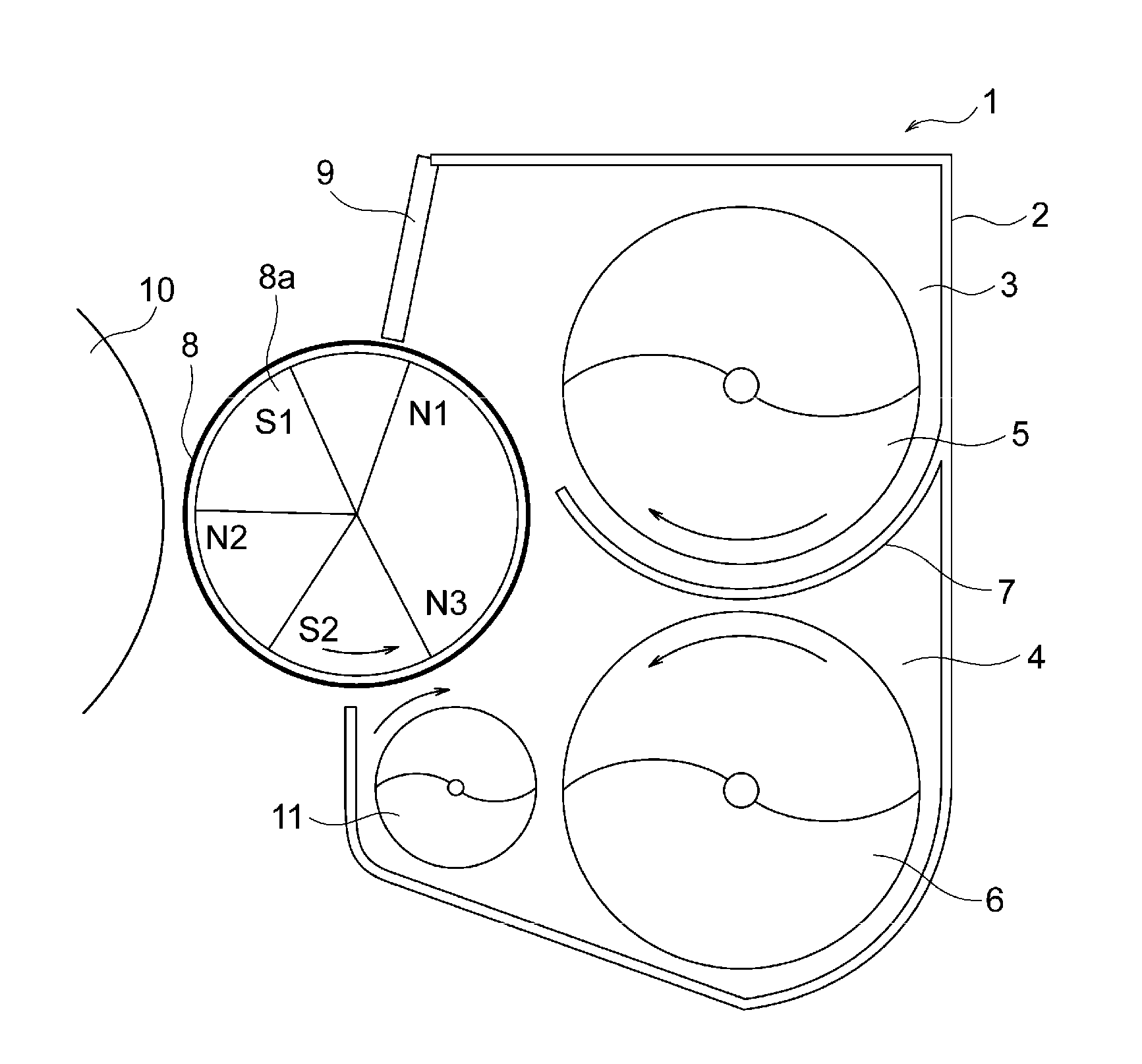
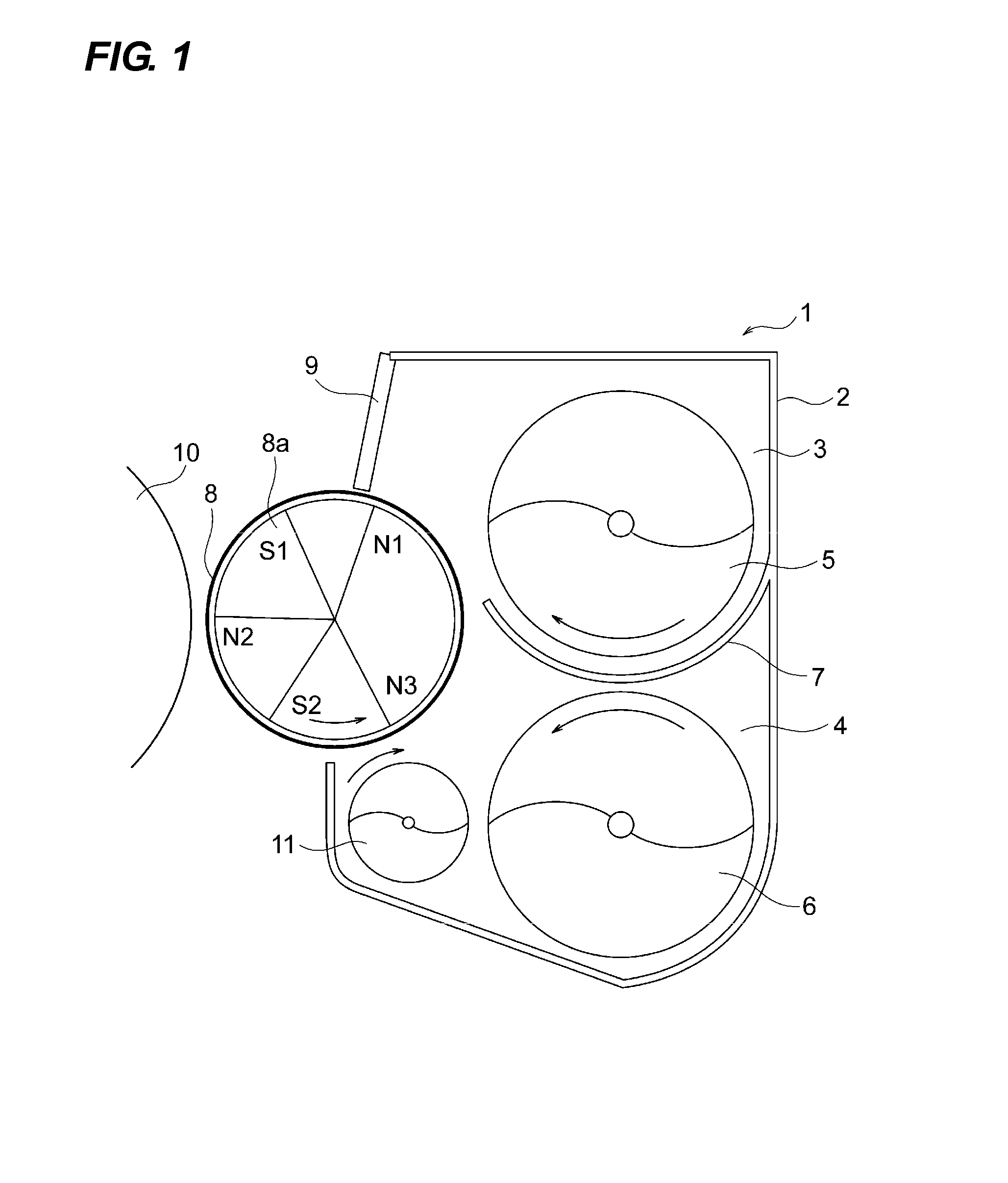
[0036]First, the developing apparatus will be described. FIG. 1 is an enlarged cross-sectional view illustrating a developing apparatus of a first embodiment. FIG. 1 illustrates a positional relation between a photosensitive drum 10 (an image bearing member) and a developing apparatus 1 in each of the stations Y, M, C, and K of a full-color image forming apparatus. The stations Y, M, C, and K have substantially the same configuration, and form image of Yellow (Y), Magenta (M), Cyan (C), Black (K) in a full-color image, respectively. In the following description, for example, the “developing apparatus 1” refers to commonly indicate a developing apparatus 1Y, a developing apparatus 1M, a developing apparatus 1C, and a developing apparatus 1K in the respective stations Y, M, C, and K as a representative.

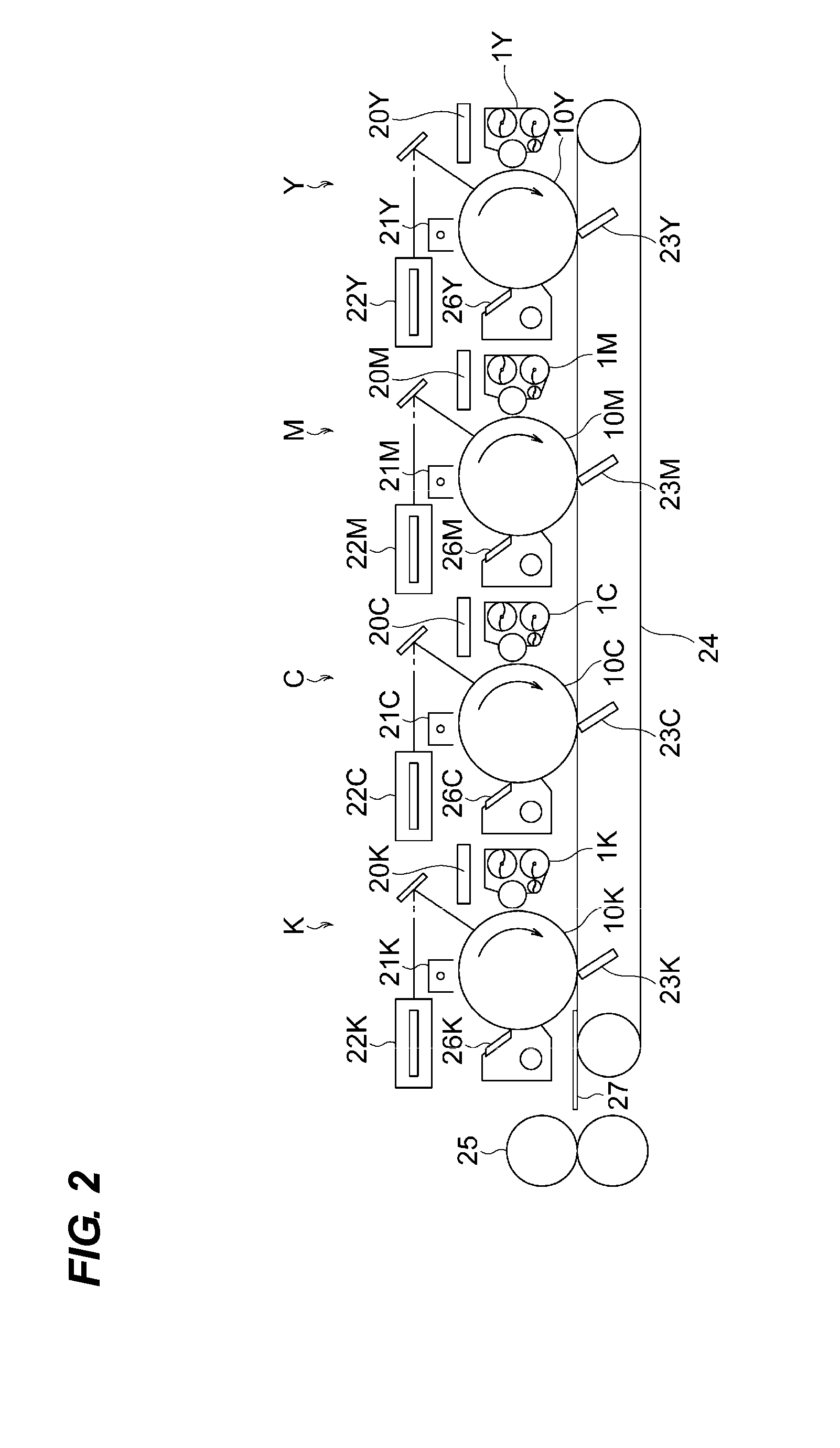
[0037]The entire operation of the image forming apparatus will be described using FIGS. 1 and 2. FIG. 2 is a schematic diagram illustrating a configuration of the image forming apparatu...

second embodiment

[0086]Next, the second embodiment will be described. In addition, basic configurations and operations of an image forming apparatus of the embodiment are the same as those of the first embodiment. Therefore, the components having the same or equivalent function or configuration will be denoted by the same reference numerals, and the detailed descriptions thereof will not be repeated. The features of the embodiment will be described below.

[0087]In the first embodiment, the conveyance performance in the downstream portion in a longitudinal direction of the third conveying screw 11 has been suppressed with respect to the upstream portion. With this configuration, the developer overflowing does not occur and the developer leakage in the downstream end portion can be reduced. However, considering that a lot of developer is conveyed to the downstream end portion of the third conveying screw 11 under the stress condition, it is desirable to provide a structure capable of making the develop...


PUM


Abstract

There is provided a developer bearing member, a supplying chamber which contains a developer to be supplied to the developer bearing member, a collecting chamber which collects the developer from the developer bearing member, a first conveying member which is disposed in the supplying chamber and conveys the developer, a second conveying member which is disposed in the collecting chamber and conveys the developer in a direction opposite to a conveying direction of the first conveying member, and a third conveying member which is disposed in the collecting chamber and conveys the developer in a direction opposite to a conveying direction of the second conveying member. The third conveying member has a conveyance performance on a downstream side lower than that on an upstream side in the conveying direction of the developer.

Description

BACKGROUND OF THE INVENTION[0001]1. Field of the Invention[0002]The present invention relates to a developing apparatus and an image forming apparatus in which an electrophotographic system or an electrostatic recording system is employed to form an image.[0003]2. Description of the Related Art[0004]Conventionally, many image forming apparatuses employing the electrophotographic system or the electrostatic recording system use a two-component developer in which toner and carrier are mixed. In particular, a full-color image forming apparatus which forms a full-color image by the electrophotographic system uses the two-component developer from a viewpoint of a coloring property and a color mixing property.[0005]A development method using the two-component developer is a method in which the toner is charged by frictional electrification between the carrier and the toner and the charged toner is attached to a latent image in an electrostatic manner to form an image.[0006]In the developm...

Claims


Application Information

Patent Timeline
Patent Type & Authority Applications(United States)
IPC IPC(8): G03G15/08G03G15/09
CPCG03G15/0889G03G15/0891G03G15/0893G03G15/09G03G2215/0833
Inventor FURUKAWA, MITSUHIRO
Owner CANON KK
Why Eureka
Try Eureka