Suture cutter
- Summary
- Abstract
- Description
- Claims
- Application Information
AI Technical Summary
Problems solved by technology
Method used
Image

Examples
Embodiment Construction
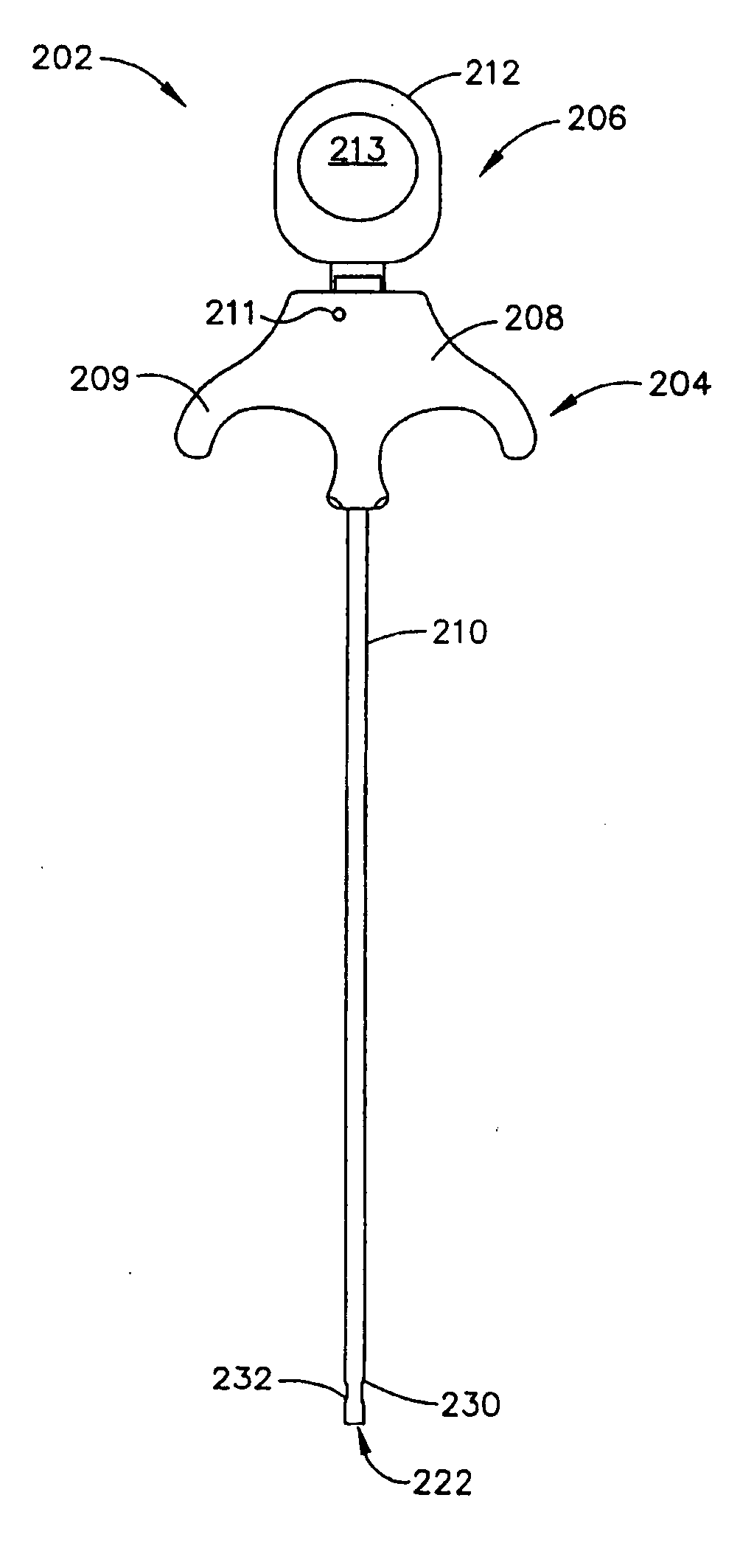
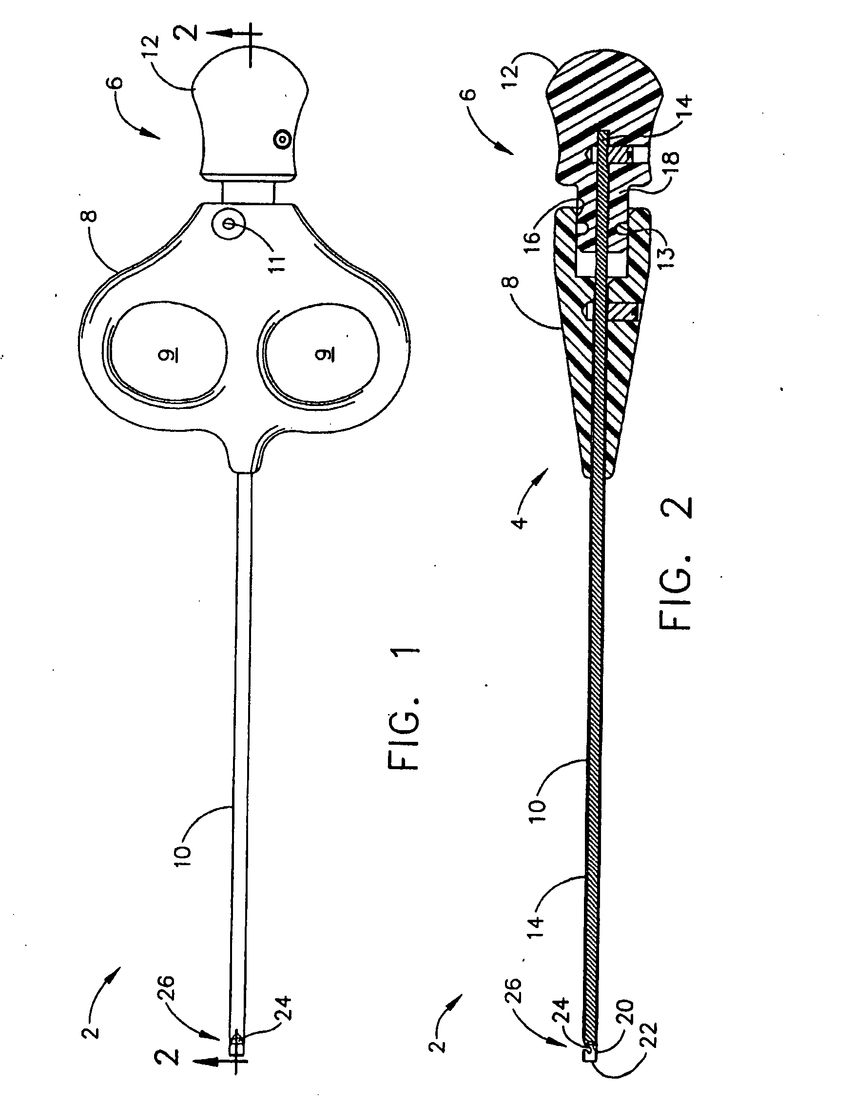
[0046] Referring now to the drawings in detail, wherein like numerals indicate the same elements throughout the views, FIG. 1 is a top view of suture cutter assembly 2 constructed according to the teachings of the present invention. FIG. 2 is a cross sectional view taken along line 2-2 of FIG. 1. Suture cutter assembly 2 includes tube assembly 4 and cutter assembly 6. Tube assembly 4 comprises grip 8 having two openings 9 for the operator's fingers. Grip 8 is secured to one end of hollow tube 10. Cutter assembly 6 includes knob 12 secured to one end of shaft 14. Although in the embodiment depicted, tube 10 is secured to grip 8 and shaft 14 is secured to knob 12 by respective set screws, any suitable means for securing them together may be used.
[0047] In the depicted embodiment, shaft 14 is rigid and solid, and dimensioned to reciprocate within rigid tube 10. The clearance between shaft 14 and tube 10 provides some resistance to axial movement of shaft 14. Grip 8 includes cylindrica...
PUM
 Abstract
Description
Claims
Application Information
 - R&D Engineer
- R&D Manager
- IP Professional
- Industry Leading Data Capabilities
- Powerful AI technology
- Patent DNA Extraction
Browse by: Latest US Patents, China's latest patents, Technical Efficacy Thesaurus, Application Domain, Technology Topic.
© 2024 PatSnap. All rights reserved.Legal|Privacy policy|Modern Slavery Act Transparency Statement|Sitemap