Injecting apparatus

a technology of injection apparatus and cannula, which is applied in the direction of intravenous devices, infusion needles, other medical devices, etc., can solve the problems of user or patient injury, increased risk of infection, and increased risk of infection, and achieve the effect of convenient automatic injection of needle cannula

Active Publication Date: 2007-05-17
WEST PHARMA SERVICES OF DELAWARE
View PDF99 Cites 120 Cited by
  • Summary
  • Abstract
  • Description
  • Claims
  • Application Information

AI Technical Summary

Benefits of technology

[0027] It is desireable to provide an injection device which facilitates automatic insertion of the needle cannula into the skin. This may be achieved by providing means for allowing the driver to drive the cartridge barrel through the housing following activation of said driver trigger and prior to movement of the stopper through the cartridge barrel, thereby urging the needle cannula outward relative to the housing and shield.

Problems solved by technology

It is well known that many people are apprehensive about receiving an injection from a needle.
This problem is even more significant for those who must administer their own medication.
A user or patient could be injured if an injection device were activated prematurely.
Such actions can cause injury if the needle pierces another person or is injected into an undesired area of the patient (e.g., an eye).
At present, there is no easy way for a patient to self-administer a dosage of drug via an automatic injection system where the dosage amount may be easily changed prior to delivery and easily delivered.
The user's inability to see the dosage form prior to use creates a significant sense of unease in the user in that the user wants to ensure that the proper dosage is in the system and ready for delivery.
More importantly, the users inability to see the dosage form prior to use leaves the user concerned that the dosage may be faulty, or, for example, have foreign particles trapped and if present, may result in injury or harm to the user.
The user's inability to view the dosage being delivered and the end of delivery leaves the user with a level of uncertainty as to the amount delivered and the delivery being completed.
The design is characterized by high complexity and costs.
The design employs a cartridge with a separate needle assembly and three springs resulting in high complexity.

Method used


Image

  • Injecting apparatus
  • Injecting apparatus
  • Injecting apparatus

Examples


Embodiment Construction

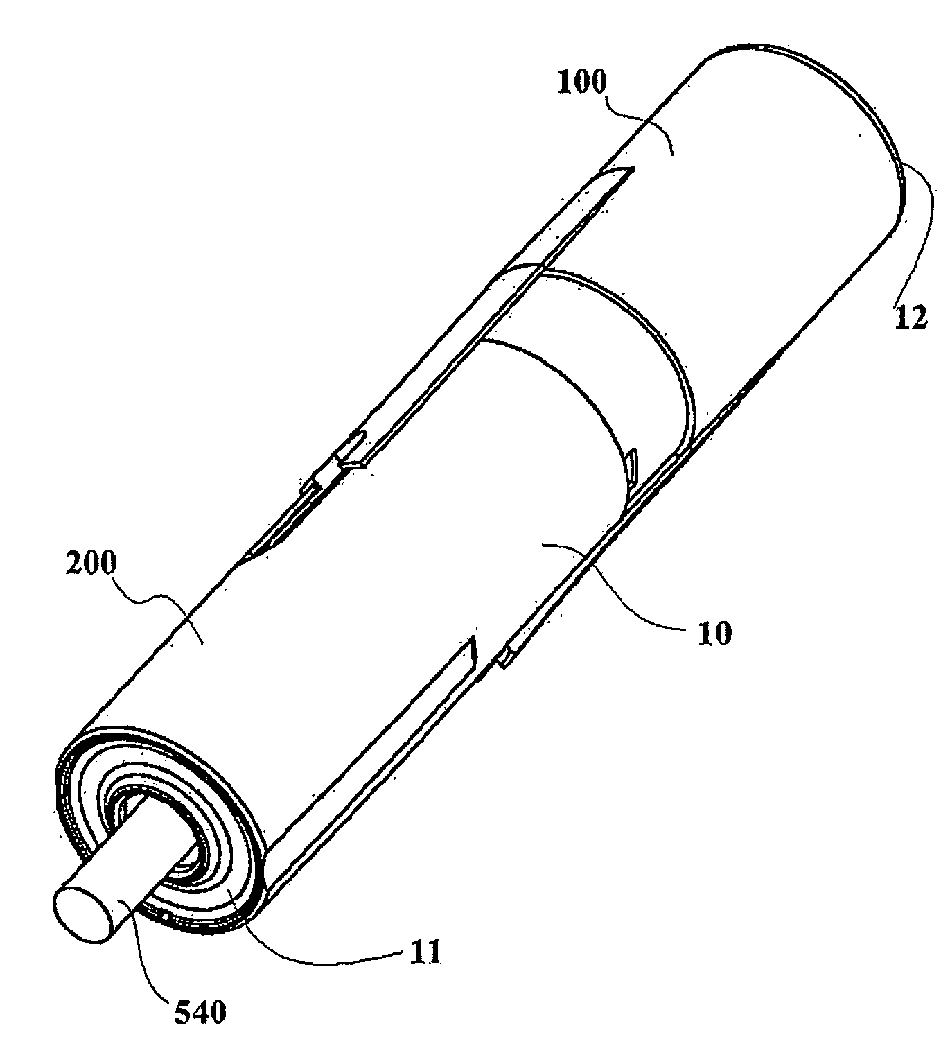
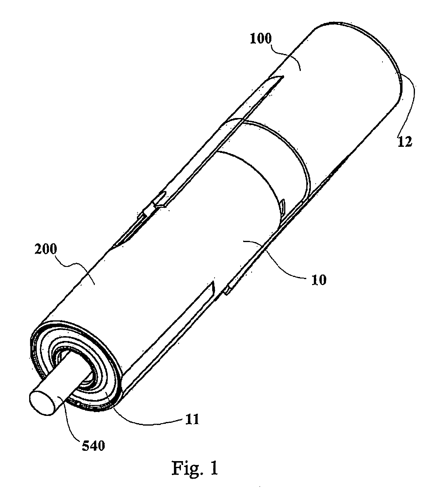
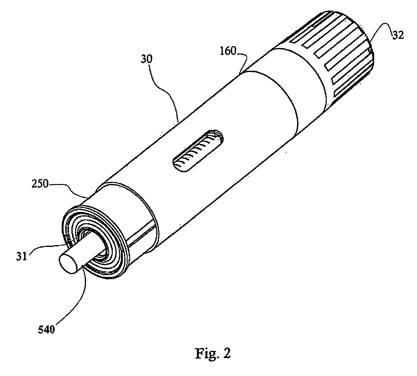
[0113] The present invention is directed to automatic injectors and needle-locking devices. The injector is automatic in that the needle at a distal end of the injector is unshielded with the user assistance; the needle is inserted into the injection site (e.g., a patient's skin) with the user assistance; delivery is automatically initiated upon insertion of the needle, and the needle is automatically shielded after the end of delivery. The exemplary injectors include a tight relationship between the position of the shield and the force required for its displacement. Moreover, the exemplary injectors include a rod that provides titration as described below.

[0114] The term distal refers to the end or direction of the injector that is applied to an injection site for delivery. The term proximal refers to the end of the injector that is opposite the distal end. The exemplary embodiments show each injector having a distal end from which the needle is exposed for delivery, and a proxima...


PUM


Abstract

An injector is automatic in that the needle is inserted into the injection site (e.g., a patient's skin) with user or caregiver assistance, the delivery is automatically initiated upon needle insertion, and the needle is retracted automatically after the end of delivery. Preferably the needle is not seen by the user prior to, during or after injection. Prior to and after injection, the needle is hidden in the device so as to avoid any potential injury or health risk to the user or health care provider. The injector includes a housing and a shield arranged to slide relative to the housing and a driver moving during drug delivery. The housing and shield form a cartridge enclosure. The cartridge is shielded and locked after delivery is completed. A needle-locking mechanism can be used in any number of pen-like injectors or safety needles.

Description

FIELD OF THE INVENTION [0001] This invention relates to the preparation and administration of a product into a living organism (e.g. the human body), and more particularly to an apparatus for automatically and safely delivering the product. DESCRIPTION OF RELATED ART [0002] Previously, various devices have been developed for the delivery of medications into and through the skin of living organisms. These devices include syringes in which a liquid drug solution is delivered through the skin of a user from a syringe chamber by movement of a syringe plunger to move the drug solution from a syringe chamber through a syringe needle inserted under the skin. The drug solution is generally in liquid form, and can be a mixture of the drug (e.g. powdered, lyophilized, concentrated liquid) and a diluent (e.g. dextrose solution, saline solution, water). [0003] It is well known that many people are apprehensive about receiving an injection from a needle. This problem is even more significant for...

Claims


Application Information

Patent Timeline
Patent Type & Authority Applications(United States)
IPC IPC(8): A61M5/00A61M5/20A61M5/32
CPCA61M5/2033A61M5/3157A61M5/3202A61M5/326A61M5/3271A61M2005/2013A61M2005/206A61M2005/2073A61M2005/2418A61M2005/3247A61M2205/581A61M2205/582
Inventor LAVI, GILADTSALS, IZRAIL
Owner WEST PHARMA SERVICES OF DELAWARE
Why Eureka
Try Eureka