Apparatus and method for facilitating the replacement of an implanted catheter

Active Publication Date: 2007-05-17
IRRAS USA INC +1
View PDF28 Cites 25 Cited by
  • Summary
  • Abstract
  • Description
  • Claims
  • Application Information

AI Technical Summary

Benefits of technology

[0008] In typical use, a physician will make an incision proximate to the patient's chest or abdomen. A surgical tunneler tool is then typically inserted through the incision to form a subcutaneous tunnel to an interior site through which a catheter can be inserted. In accordance with a preferred embodiment, a sleeve, an annular seal, and a compression member, are mounted on the catheter as previously described. The distal end of the sleeve is then inserted through the incision to locate the sleeve porous layer in contact with the dermis just below the patient's outer skin surface. The sleeve proximal end is then preferably anchored adjacent to the patient's exterior skin surface. With the sleeve anchored and the compression member in its unlocked state, the physician is able to slide and/or rotate the catheter within the sleeve for optimum catheter positioning. When the catheter is properly positioned, the annular seal is moved along the catheter against the sleeve proximal end to engage a portion in the wedge recess. The compression member can then be brought up against and latched to the sleeve thus compressing the seal therebetween and preventing relative movement between the catheter and sleeve. With the sleeve thus implanted, the patient's subcutaneous tissue will, over time, grow into the porous material to anchor the sleeve and form an infection resistant barrier. The porous material may be coated or impregnated with constituents having antimicrobial and/or anti-inflammatory properties to promote healing, e.g., silver containing compounds or antibiotic eluting coatings and/or steroids.
[0009] In one preferred embodiment of the invention, the porous layer on the sleeve is covered prior to use by a protective sheath of thin flexible material. The sheath prevents abrasion damage as the sleeve porous layer is inserted through the incision. The sheath is preferably configured with a projecting tab which allows the physician to readily peel the sheath away, e.g., along a preformed score line, as the sleeve is inserted through the incis

Problems solved by technology

Unless adequate precautions are taken, infections and inflammation are likely to occur around the site where the catheter penetrates the skin.
Although such a cuff can reduce the likelihood of infection, its presence increases the difficulty of r

Method used


Image

  • Apparatus and method for facilitating the replacement of an implanted catheter
  • Apparatus and method for facilitating the replacement of an implanted catheter
  • Apparatus and method for facilitating the replacement of an implanted catheter

Examples


Example

[0021] Various medical regimens utilize a percutaneously implanted flexible elongate conduit to provide access to an interior body site. For example, hemodialysis drug infusion, plasmapheresis, and other procedures typically employ a percutaneously implanted catheter for delivering fluid to or extracting fluid from an interior body site. Other procedures utilize an electric cable to deliver an electric signal to, or extract an electric signal from, an interior body site. The present invention is directed to a method and apparatus for facilitating the long term implantation and utilization of a flexible elongate conduit and for facilitating the positioning, repositioning, and replacement , or exchange, of the conduit.

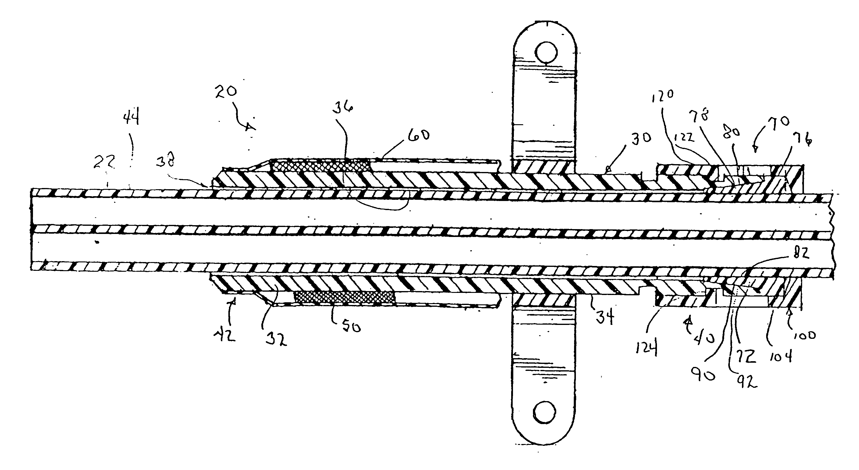
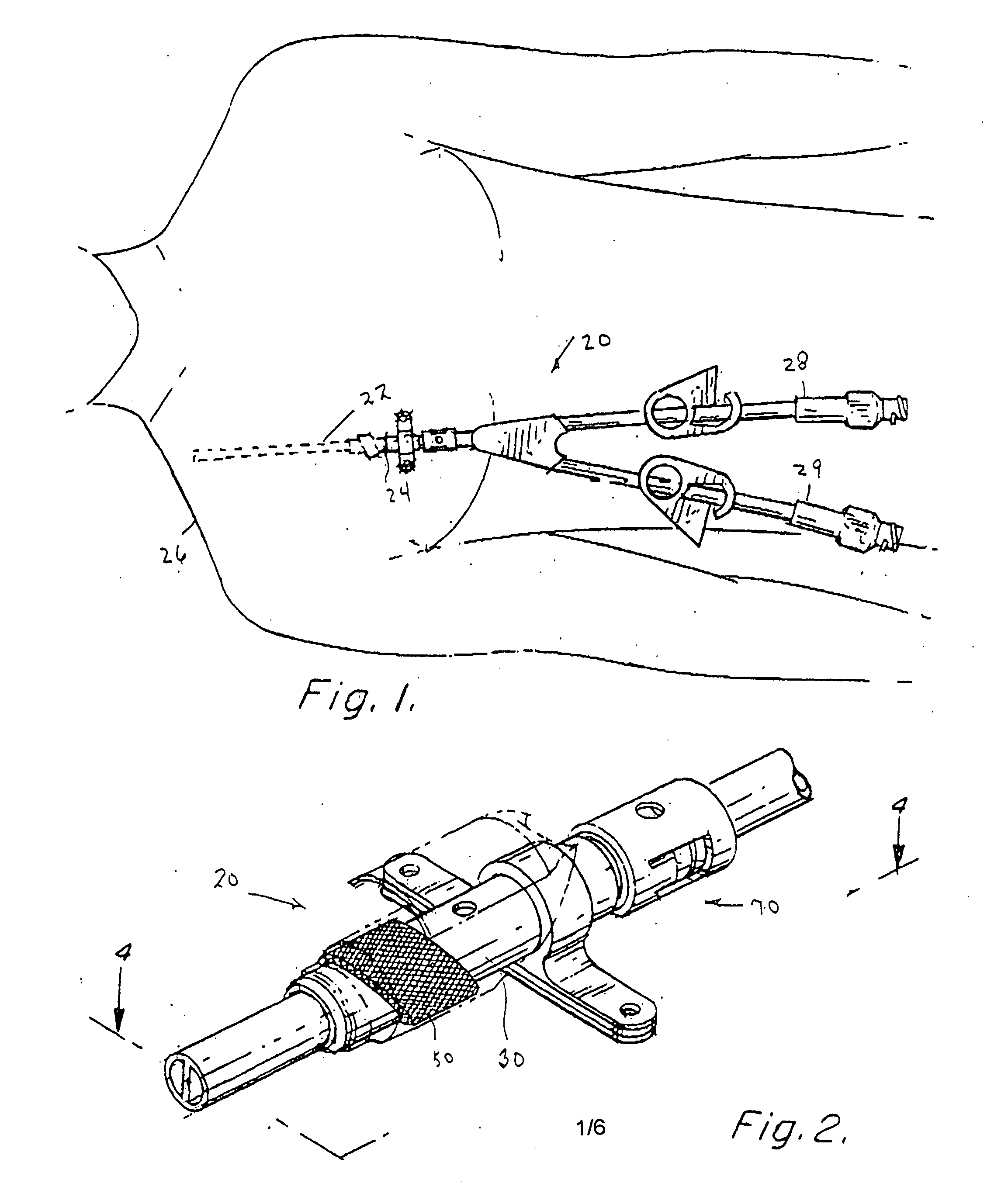
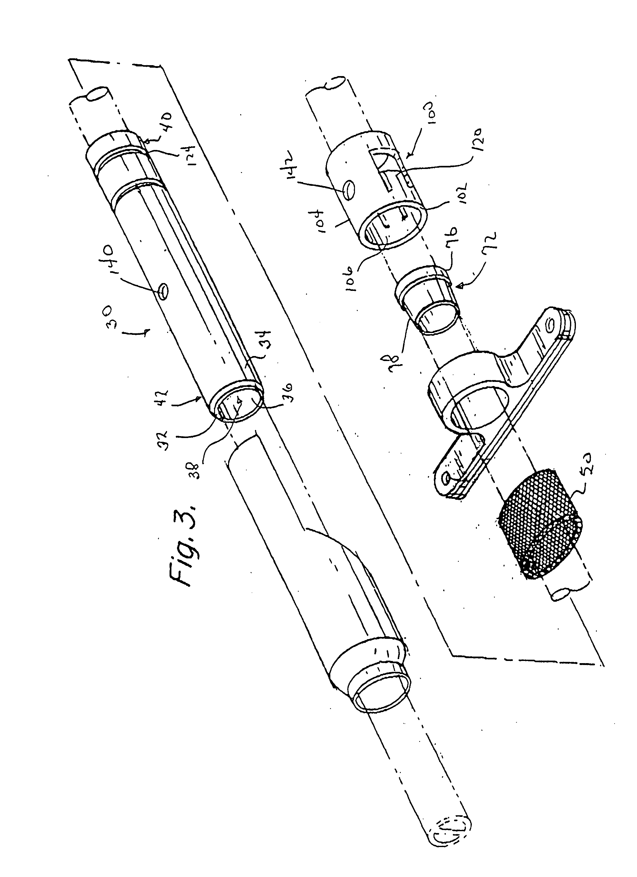
[0022]FIG. 1 schematically depicts an apparatus 20 in accordance with the invention for percutaneously implanting a catheter 22 through an incision 24 in a patient 26 undergoing an exemplary hemodialysis procedure. In such a procedure, a dual lumen catheter 22 is typica...


PUM


Abstract

A medical apparatus and method of use for implanting a percutaneous catheter in a patient's body which catheter can be easily positioned, repositioned, and replaced. The apparatus includes an elongate sleeve comprising a wall surrounding an interior elongate passageway. The passageway extends from a sleeve proximal end to a sleeve distal end. The sleeve is intended to be percutaneously implanted through an incision in the patient's skin so that the sleeve distal end resides subcutaneously. The sleeve outer peripheral surface carries a layer of porous material intended to be placed just under the patient's outer skin layer in contact with the dermis to promote tissue ingrowth for anchoring the sleeve and forming an infection resistant barrier. The sleeve passageway is dimensioned to snugly accommodate the outer surface of catheter while permitting the catheter to slide relative to the sleeve. A sealing device is mounted around the catheter adjacent to the sleeve proximal end to prevent deleterious material from migrating into the patient's body along the catheter outer surface.

Description

RELATED APPLICATIONS [0001] This application is a Continuation-In-Part of U.S. application Ser. No. 10 / 821,383 filed on Apr. 9, 2004 which claims priority based on U.S. Provisional Application Ser. No. 60 / 462,265 filed on Apr. 12, 2003. This application claims priority based on the aforementioned applications, whose disclosures are, by reference, incorporated herein and on U.S. Provisional Application Ser. No. 60 / 758,137 filed on Jan. 11, 2006.FIELD OF THE INVENTION [0002] This invention relates generally to medical technology and more particularly to a method and apparatus for implanting an elongate conduit, e.g., a catheter or cable, so as to extend through a patient's skin for providing long term access to an interior body site. Embodiments of the invention are useful in a variety of applications, e.g., in hemodialysis procedures to provide access to the patient's central venous system. BACKGROUND OF THE INVENTION [0003] In a variety of medical procedures, catheters are implanted...

Claims


Application Information

Patent Timeline
IPC IPC(8): A61M39/02A61F2/00A61M1/00
CPCA61F2/0077A61L29/146A61M39/0247A61M2039/0261H04R2225/67
Inventor PORTER, CHRISTOPHER H.VIDAL, CLAUDE A.REDMOND, RUSS J.MORAN, BYRON L.KALUZNIAK, PAULJANIS, ABRAM D.
Owner IRRAS USA INC
Why Eureka
Try Eureka