Press Brake Tool Safety Key Assemblies

a technology of safety key and press brake, which is applied in the direction of manufacturing tools, shaping tools, metal-working apparatus, etc., can solve the problems of damage to equipment, accidental slip and fall of punches on the upper table of press brakes, and damage to press brake operators

Active Publication Date: 2007-06-28
WILSON TOOL INT
View PDF23 Cites 23 Cited by
  • Summary
  • Abstract
  • Description
  • Claims
  • Application Information

AI Technical Summary

Benefits of technology

[0012] In the present embodiments, the tool includes a lock that is in a locked position such that the safety key is positively locked in its extended position. Further, in the present embodiments, the tool has a button that can be pushed by a press brake operator so as to move the lock from its locked position to an unlocked position. In these embodiments, pushing the button results in the safety key's trailing cam surface resting on the generally upwardly-facing shoulder so as to hold / maintain the tool in the tool holder's recess until the operator pulls downwardly on the tool so as to cause the safety key's trailing cam surface to cam with said generally upwardly-facing shoulder thereby moving the safety key from its extended position toward its retracted position and allowing the tool to be removed downwardly from the tool holder's recess.

Problems solved by technology

However, punches mounted on the upper table of a press brake often are not so easily replaced.
When the clamp is loosened to the point where the punch can be removed downwardly, the punch may accidentally slip and fall.
This can cause harm to press brake operators and / or damage to equipment, particularly when using long punches (which can be quite heavy).
This is less than ideal in some respects.
For example, when a tool is being positioned or repositioned on a tool holder (e.g., when sliding the tool along the tool holder), it may be difficult to assure the spring will keep the safety key engaged with the tool holder at all times. This may be particularly difficult to assure if the spring force weakens substantially over time.
Inadvertent retraction of the safety key may otherwise cause the tool to fall unexpectedly from the tool holder.

Method used


Image

  • Press Brake Tool Safety Key Assemblies
  • Press Brake Tool Safety Key Assemblies
  • Press Brake Tool Safety Key Assemblies

Examples


Embodiment Construction

[0063] The following detailed description is to be read with reference to the drawings, in which like elements in different drawings have like reference numerals. The drawings, which are not necessarily to scale, depict selected embodiments and are not intended to limit the scope of the invention. Skilled artisans will recognize that the examples provided herein have many useful alternatives that fall within the scope of the invention.

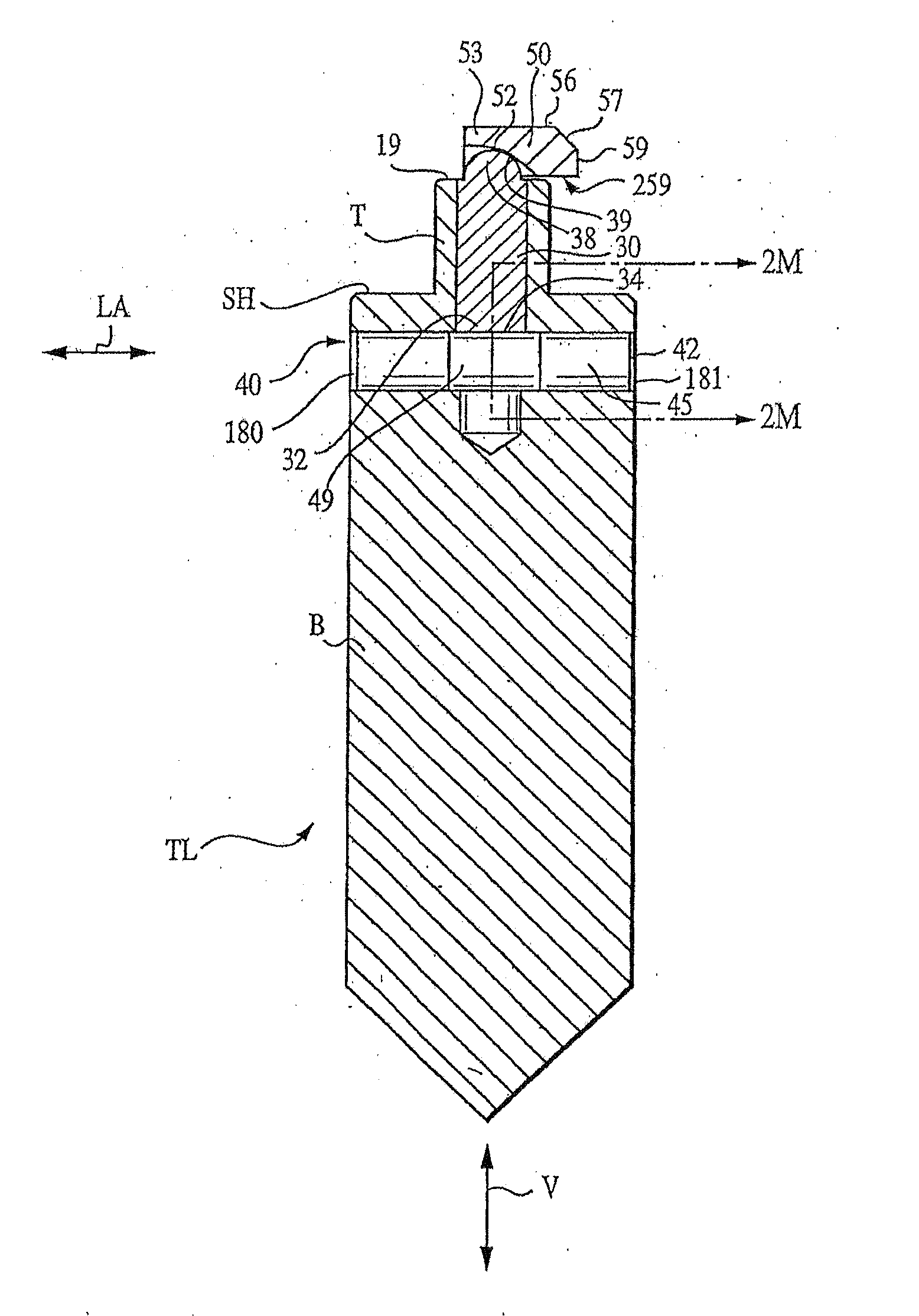
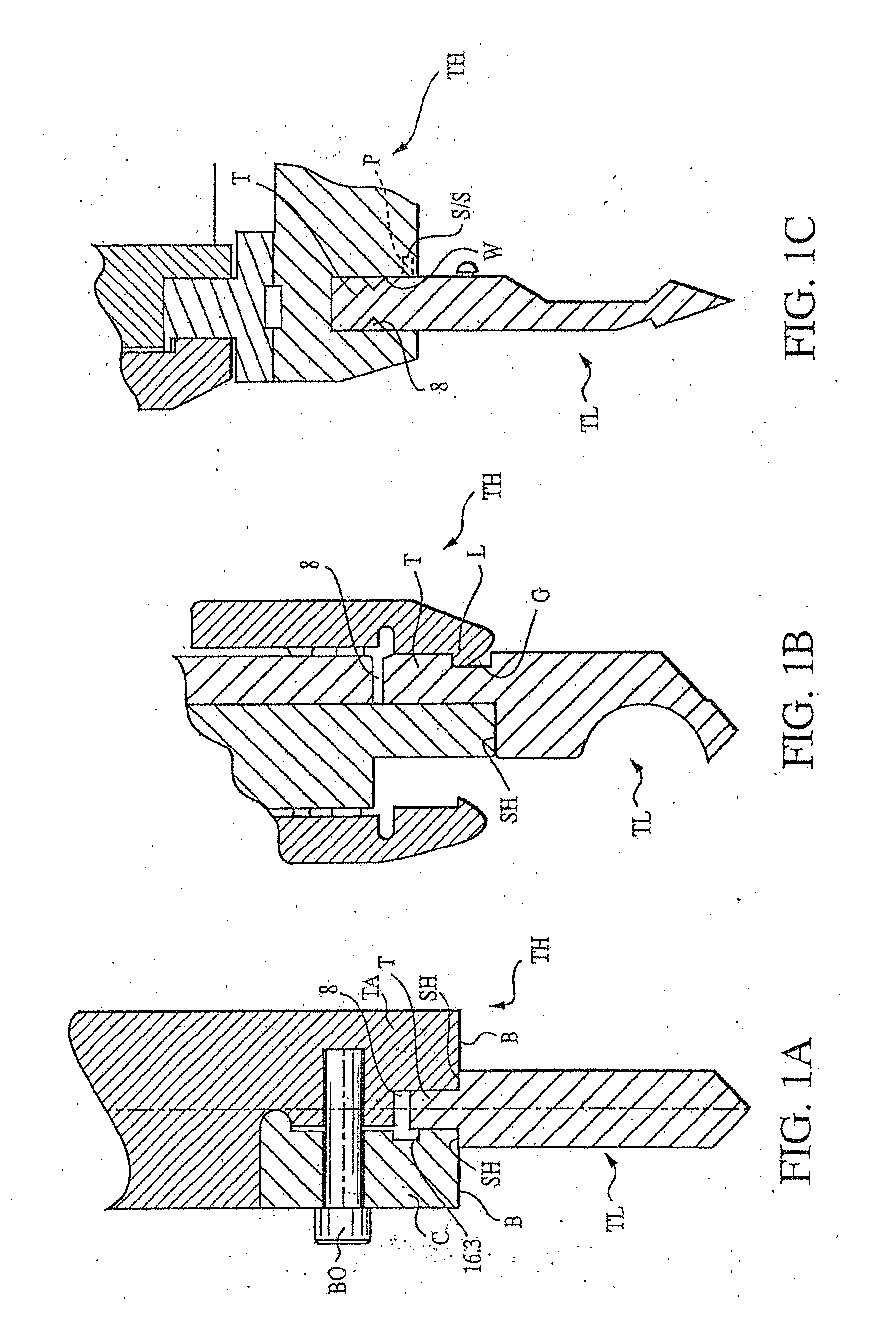
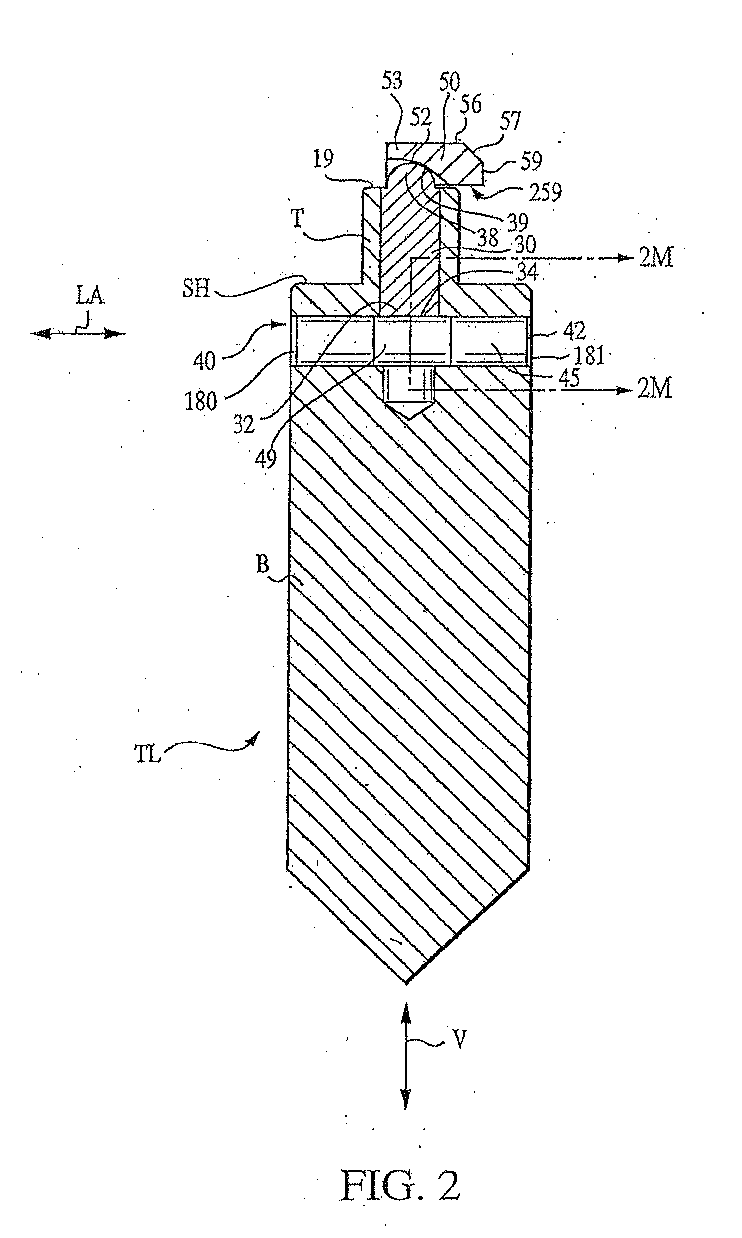
[0064] The invention provides a press brake tool that has a lockable safety key. The press brake tool can be of any desired tooling style, including well-known styles such as the American, Wila, and European styles. The American and Wila styles are described above and illustrated respectively in FIGS. 1A and 1C. The European style, which is also well known in the present art, is illustrated in FIG. 1B. The press brake tool can also take the form of various other tooling styles that are known in the art but are currently in less widespread use. In fact...


PUM

PropertyMeasurementUnit
angleaaaaaaaaaa
angleaaaaaaaaaa
angleaaaaaaaaaa

Abstract

The invention provides a press brake tool having a retractable safety key. In some embodiments, the tool includes a lock that can positively lock the safety key in an extended position. Different lock assemblies of this nature are provided. Also provided is a combination including a press brake tool and a tool holder. In some embodiments, the invention provides a press brake tool having a retractable safety key with an engagement portion having a tapered leading region (adapted to facilitate mounting the tool in a recess of a tool holder) and a tapered trailing region (adapted to facilitate dismounting the tool from the recess of the tool holder). Methods of use are also provided.

Description

RELATED APPLICATIONS [0001] This application is a continuation-in-part of U.S. patent application Ser. No. 11 / 361,604, filed Feb. 24, 2006, titled Press Brake Tool Having Lockable Safety Key, which is a continuation of U.S. patent application Ser. No. 10 / 611,181, filed Jul. 1, 2003, also titled Press Brake Tool Having Lockable Safety Key, now issued as U.S. Pat. No. 7,004,008, the entire teachings of each of which are incorporated herein by reference.FIELD OF THE INVENTION [0002] The present invention relates generally to press brake tools. More particularly, this invention relates to press brake tools that have safety keys. BACKGROUND OF THE INVENTION [0003] Press brakes are commonly used to shape sheet-like workpieces, such as sheet metal and the like. A conventional press brake has an upper beam and a lower beam, at least one of which is movable toward and away from the other. Typically, the upper beam is movable vertically while the lower beam is fixed in a stationary position. ...

Claims


Application Information

Patent Timeline
Patent Type & Authority Applications(United States)
IPC IPC(8): B21D37/00
CPCB21D5/0209
Inventor SHIMOTA, JON M.ROGERS, BRYAN L.
Owner WILSON TOOL INT
Why Eureka
Try Eureka