Post and rod linking device for a railing

a technology of linking device and railing, which is applied in the direction of rod connection, building type, construction, etc., can solve the problems of two ends of the fastening member and undecent looking, and achieve the effect of easy and quick linkage of posts

Inactive Publication Date: 2007-07-12
LO CHONG YI
View PDF7 Cites 26 Cited by
  • Summary
  • Abstract
  • Description
  • Claims
  • Application Information

AI Technical Summary

Benefits of technology

[0005] This invention has been devised to offer a post and rod linking device for a railing so as to easily and quickly link posts and rods for a railing.

Problems solved by technology

In linking posts with rods of a railing, conventionally screws or bolts are used for linking posts with rods, requiring much time for tightening fastening members such as screws or bolts, and moreover, the two ends of the fastening members are always exposed out, not decent to be looked at.

Method used


Image

  • Post and rod linking device for a railing
  • Post and rod linking device for a railing
  • Post and rod linking device for a railing

Examples


Embodiment Construction

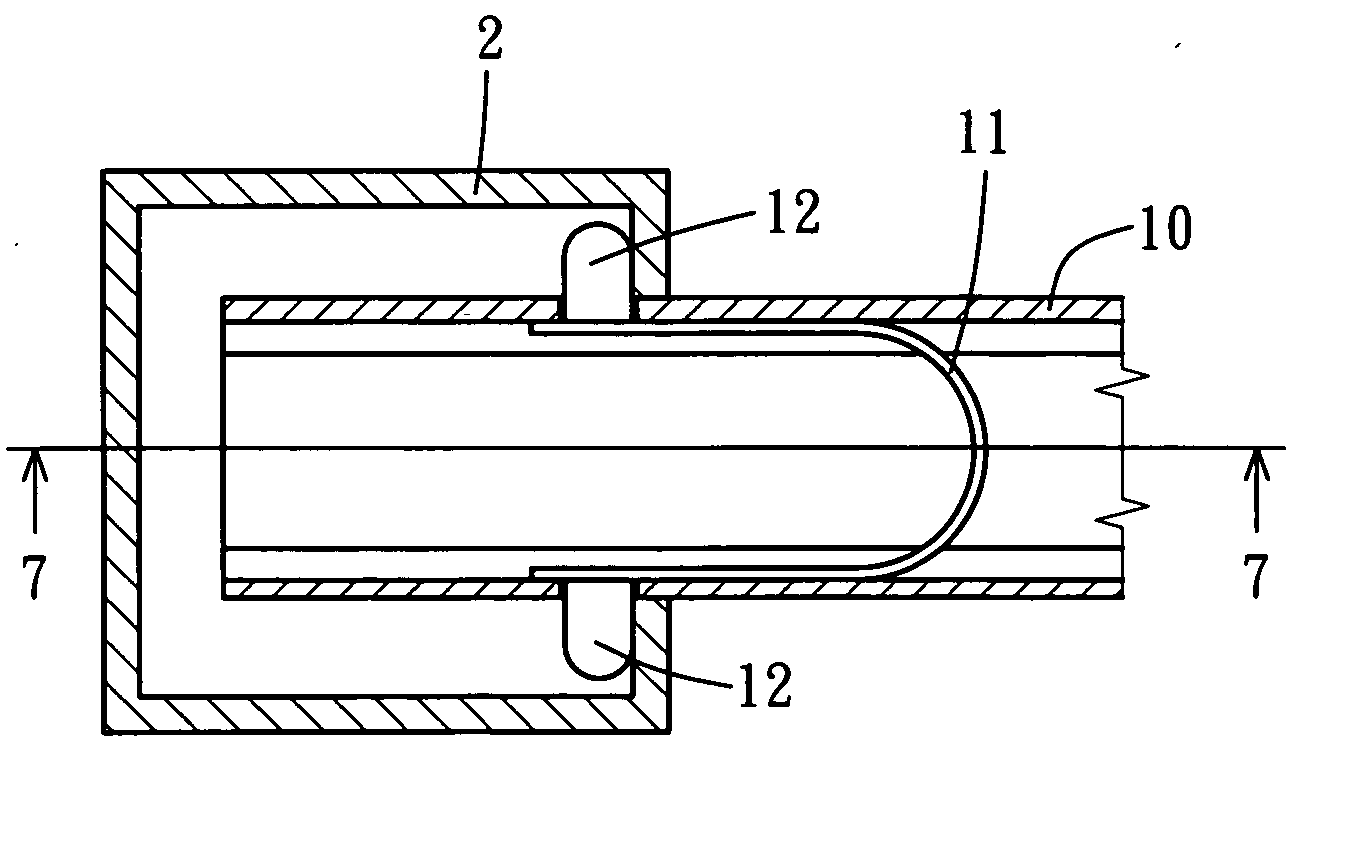
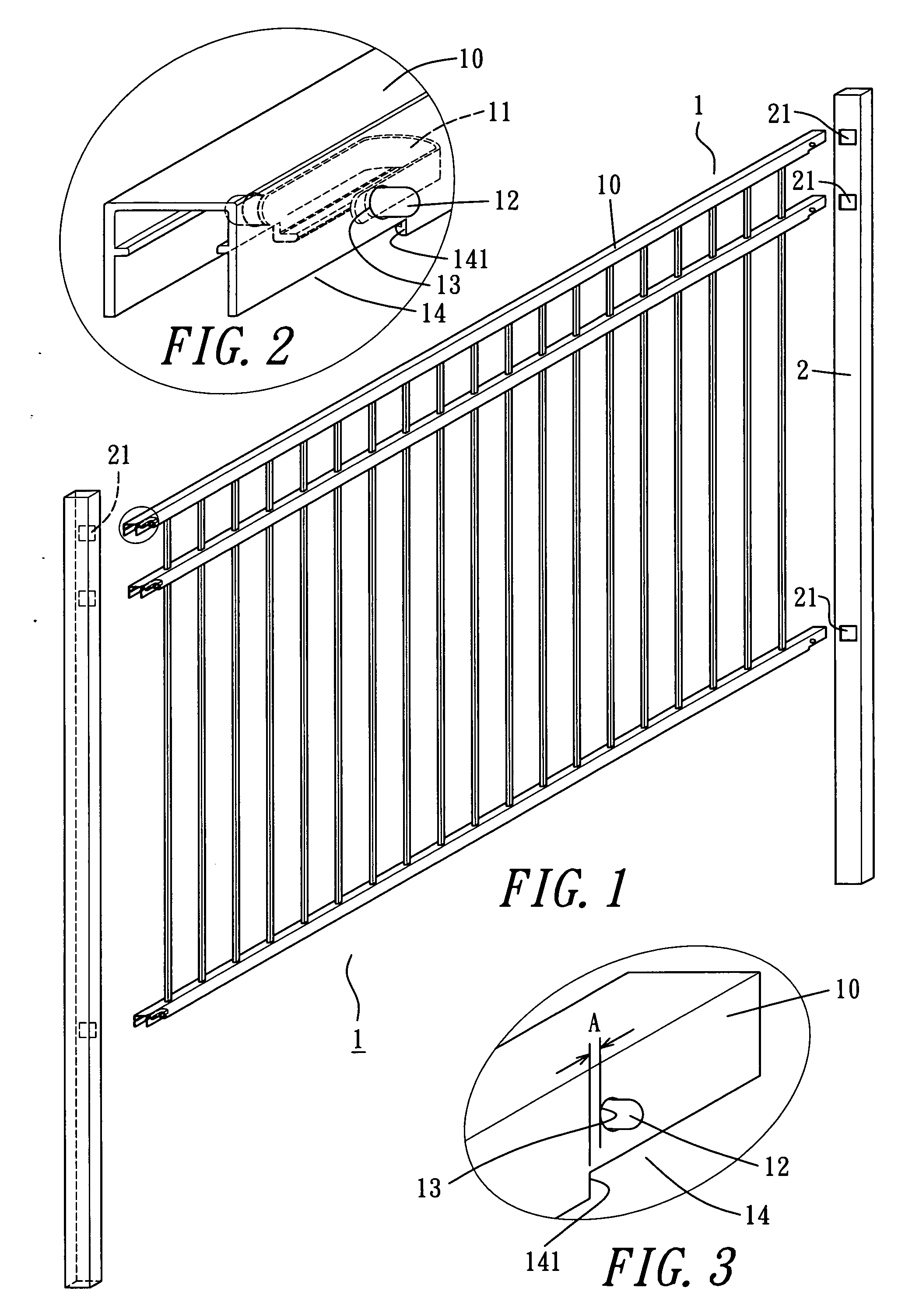
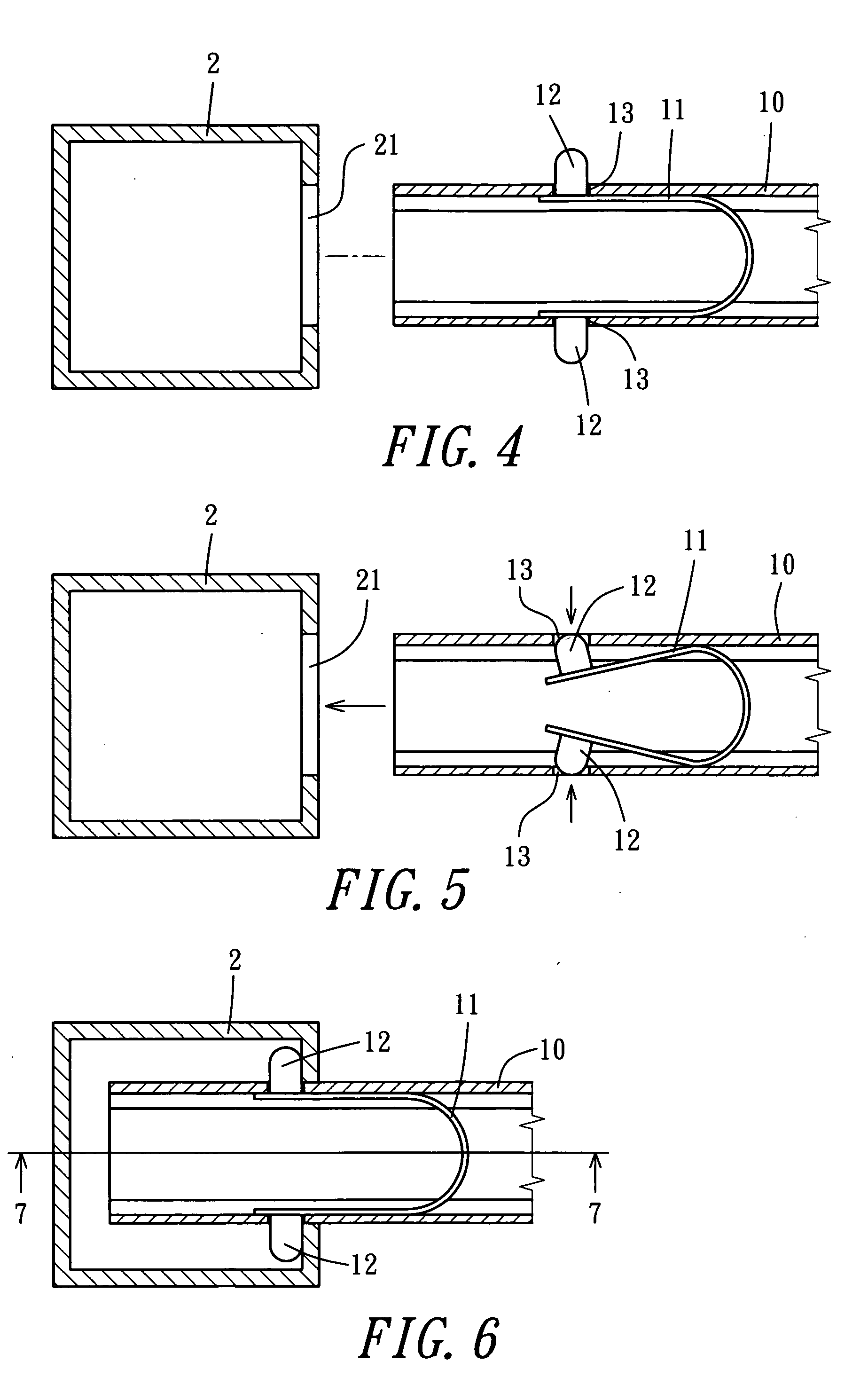
[0015] A preferred embodiment of a post and rod linking device for a railing in the present invention, as shown in FIGS. 1, 2 and 3, includes a lateral rod 10 of railing rods 1, two posts 2 at two sides of the lateral rod 10, a U-shaped elastic member 11 deposited respectively in two ends of the lateral rod 10.

[0016] The U-shaped elastic member 11 is provided with a round protrusion 12 respectively on an outer side of two ends

[0017] The lateral rod 10 is provided with a hole 13 respectively near the two ends to correspond to the round protrusion 12 of the U-shaped elastic member 11 so that the round protrusions may expose out of the lateral rod 12 pushed by the elasticity of the U-shaped elastic member 11. Further, the lateral rod 10 is provided with a recess 14 in a bottom wall of the two ends, and there is a distance (A) between a vertical surface 141 defining the recess 14 and the protrusion 12, as shown in FIG. 3.

[0018] The post 2 is provided with an insert hole 21 in a side ...


PUM


Abstract

A post and rod linking device for a railing includes a lateral rod, a post and a U-shaped elastic member. The elastic member is deposited in each of two ends of the lateral rod, having a protrusion respectively on two ends. The protrusion faces and exposes out of a hole of the lateral rod by the elastic member, The post has an insert hole for each end of the lateral rod to fit there in, with the protrusions of the elastic member pressed inward and extending out of the holes after the lateral rod is inserted in the hole of the post and stopped by the post wall so that the lateral rod is linked with the post immovable. The end of the lateral rod has a recess, which has a vertical surface, and the distance between the vertical surface and the protrusion is equal to the thickness of the post wall so the post wall is clamped by the elastic member to stabilize the linking of the post with the lateral rod.

Description

BACKGROUND OF THE INVENTION [0001] 1. Field of the Invention [0002] This invention relates to a post and rod linking device for a railing, particularly to one quite easily handled for linking posts with rods with no linking components exposed out. [0003] 2. Description of the Prior Art [0004] In linking posts with rods of a railing, conventionally screws or bolts are used for linking posts with rods, requiring much time for tightening fastening members such as screws or bolts, and moreover, the two ends of the fastening members are always exposed out, not decent to be looked at. SUMMARY OF THE INVENTION [0005] This invention has been devised to offer a post and rod linking device for a railing so as to easily and quickly link posts and rods for a railing. [0006] The feature of the invention is a lateral rod of railing rods having its two ends provided with a U-shaped elastic member, and the U-shaped elastic member has a round projection respectively on an outer side of two ends. The...

Claims


Application Information

Patent Timeline
Patent Type & Authority Applications(United States)
IPC IPC(8): E04H17/14
CPCF16B7/0473E04F11/181E04F2011/1821E04F11/1817
Inventor LO, CHONG-YI
Owner LO CHONG YI
Why Eureka
Try Eureka