

Image capturing method and image-capturing device thereof
- Summary
- Abstract
- Description
- Claims
- Application Information
AI Technical Summary
Benefits of technology
Problems solved by technology
Method used
Image

Examples
first embodiment
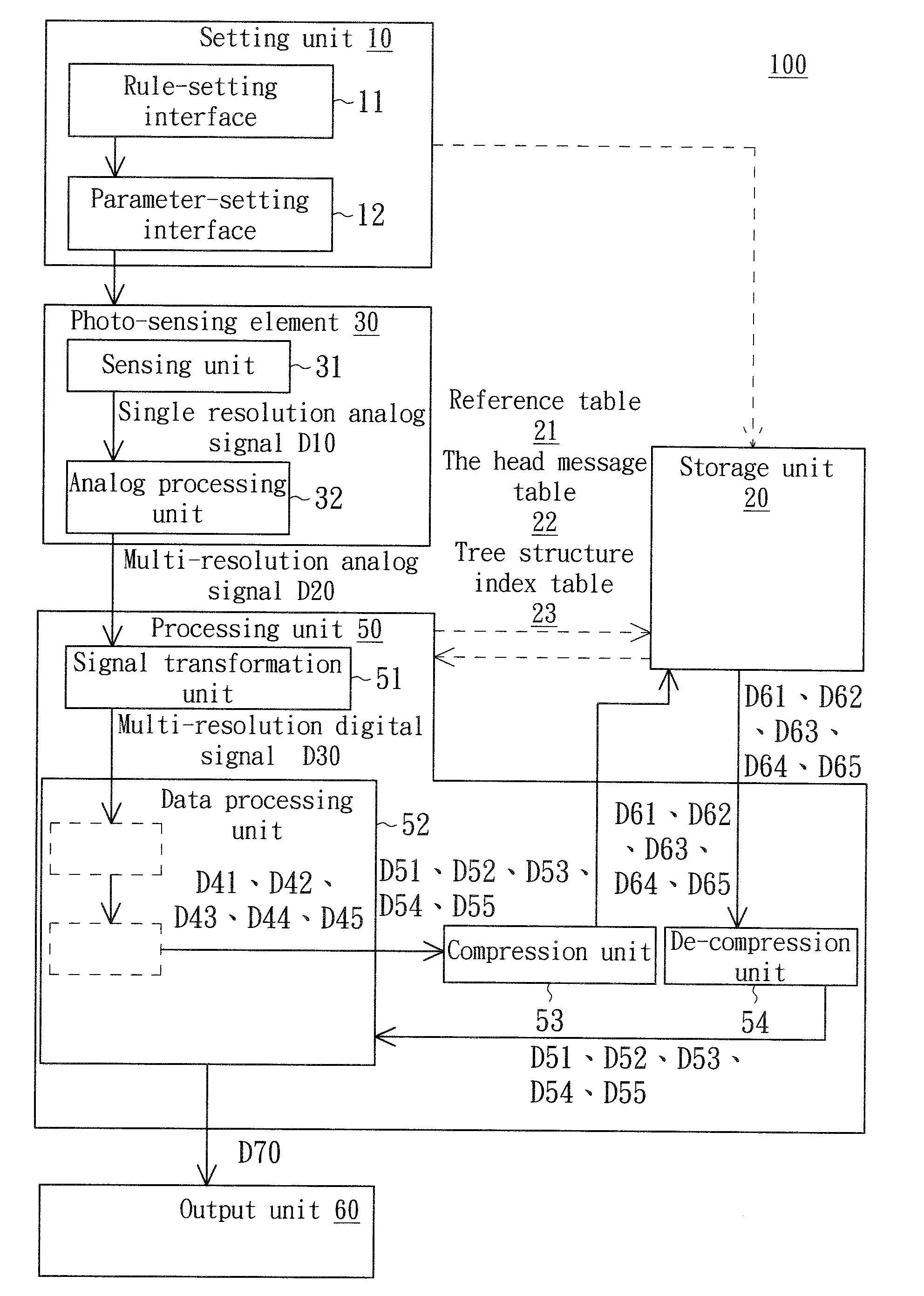
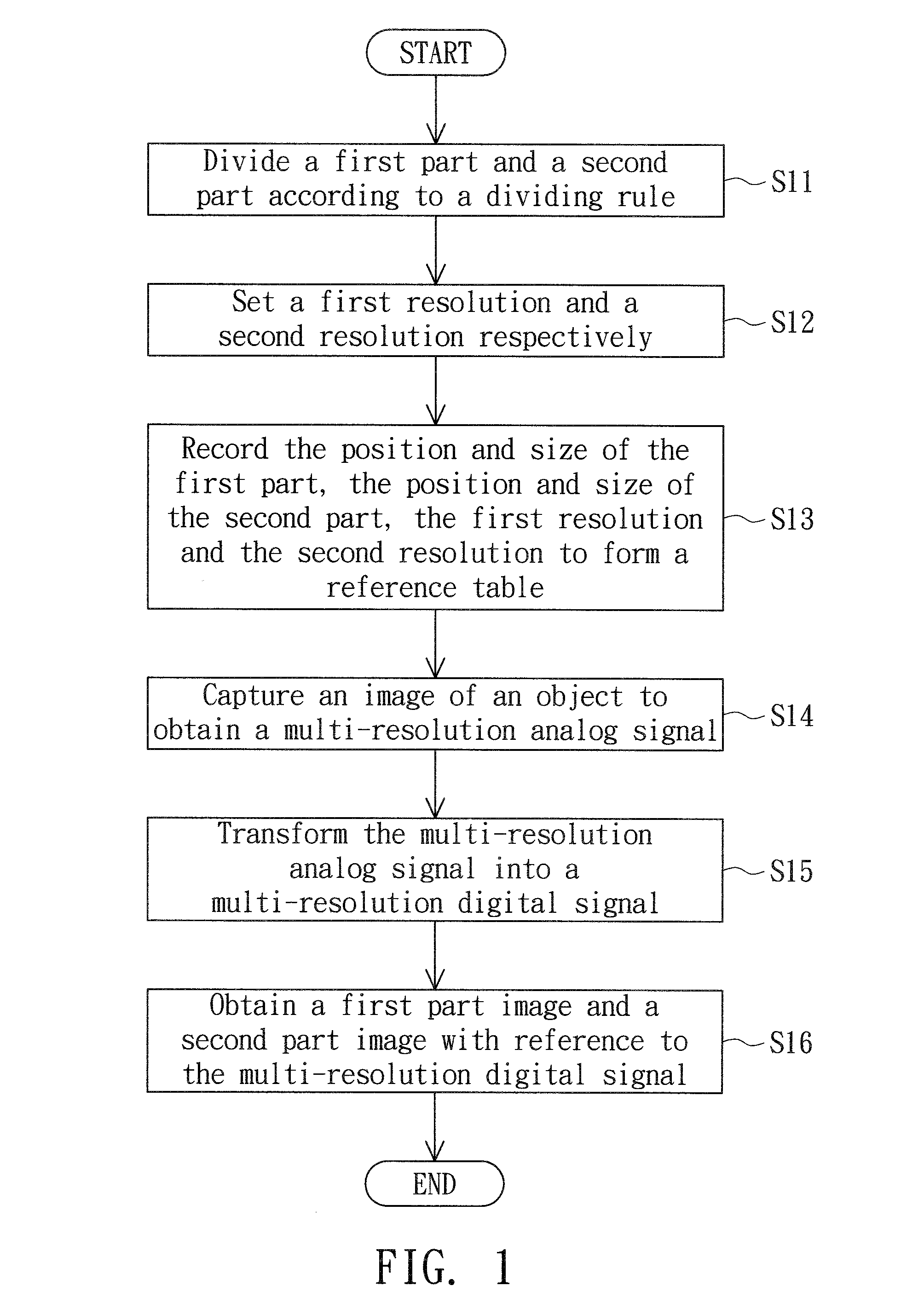
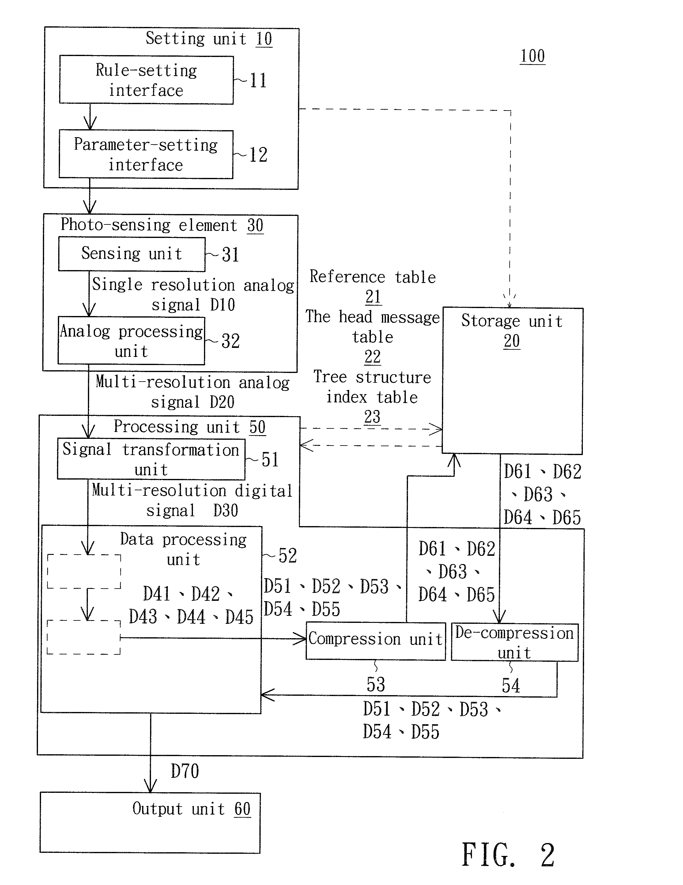
[0023]Referring to both FIGS. 1˜2. FIG. 1 is a flowchart of an image capturing method according to a first embodiment of the invention. FIG. 2 is a block diagram of an image-capturing device according to the first embodiment of the invention. The image-capturing device 100 of the present embodiment of the invention is exemplified by a scanner. As indicated in FIG. 2, the image-capturing device 100 comprises a setting unit 10, a photo-sensing element 30, a processing unit 50 and a storage unit 20. The setting unit 10 comprises a rule-setting interface 11 and a parameter-setting interface 12. The photo-sensing element 30 comprises a sensing unit 31 and an analog processing unit 32. The processing unit 50 comprises a signal transformation unit 51, a data processing unit 52, a compression unit 53 and a decompression unit 54.
[0024]Firstly, the method begins at step S11 of FIG. 1, and also refers to FIG. 3. FIG. 3 is a perspective of the first to the fifth parts. In the step S11, a dividi...
second embodiment
[0048]Referring to FIG. 9, a block diagram of an image-capturing device according to a second embodiment of the invention is shown. The image capturing method of the present embodiment of the invention and the image-capturing device 200 thereof differ with the image capturing method of the first embodiment and the image-capturing device 100 thereof in the photo-sensing element 40 and the method of obtaining the multi-resolution analog signal D20. As for the similar elements, the same reference numbers are used and are not repeated here.
[0049]The photo-sensing element 40 of the present embodiment of the invention supports multi-resolution signal scanning function. Referring to both FIG. 3 and FIG. 10. FIG. 10 is a diagram of a multi-resolution analog signal along the scan line 10-10′ of FIG. 3. In FIG. 3, the scan line 10-10′ sequentially passes through the first part part1, the fourth part part4, the first part part1, the third part part3 and the first part part1. As indicated in FI...
PUM
 Abstract
Description
Claims
Application Information