Electric motor and electric power steering apparatus

Inactive Publication Date: 2007-09-06
HONDA MOTOR CO LTD
View PDF48 Cites 15 Cited by
  • Summary
  • Abstract
  • Description
  • Claims
  • Application Information

AI Technical Summary

Benefits of technology

[0034]With this configuration, vibration of the rotation shaft can be prevented during the actuation of the electric motor. Therefore, excellent steering feeling can be obtained.
[0035]According to the present invention, even if a force is generated in the radial direction during the rotation of the rotation shaft, since there are no gaps between the inner race of each rolling bearing and the outer peripheral surface of the rotation shaft and between the outer race of each rolling bearing and the inner peripheral surface of the bearing attachment portion, it is possible to reliably prevent a generation of vibration on the rotation shaft. Further, since the electric motor is provided with the displacement restriction member, a displacement of the rolling bearing in the axial dir

Problems solved by technology

The conventional electric power steering apparatus has a drawback that the rotation shaft (output shaft) of the electric motor as a drive source displaces in the axial direction.
However, once the electric motor of the electric power steering apparatus is driven, due to unbalance of magnetic force or unbalance of the rotation shaft per se, a greater force (centrifugal force) is generated in the radia

Method used


Image

  • Electric motor and electric power steering apparatus
  • Electric motor and electric power steering apparatus
  • Electric motor and electric power steering apparatus

Examples


Example

First Embodiment

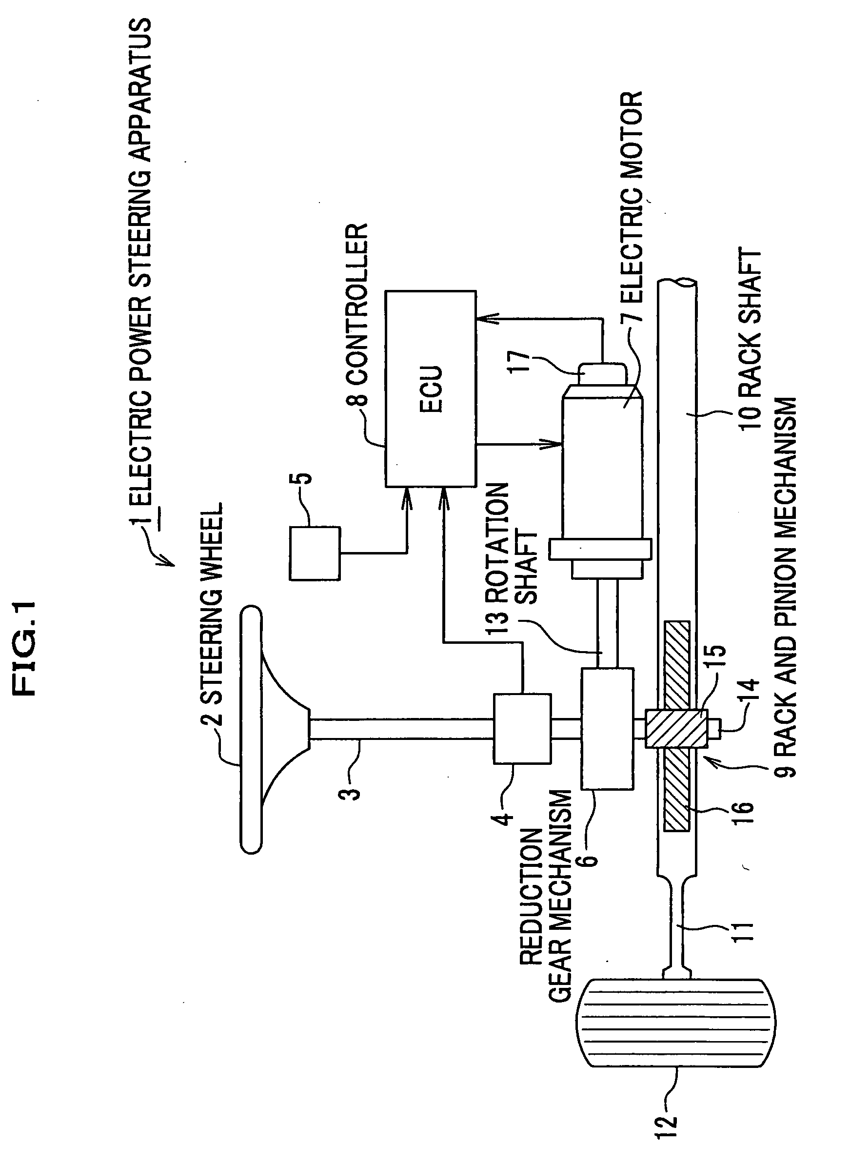
[0053]As seen in FIG. 1, an electric power steering apparatus 1 according to this preferred embodiment includes a steering shaft 3 connected with a steering wheel 2, a steering torque sensor 4 for detecting a steering torque applied to the steering shaft 3, a vehicle speed sensor 5 for detecting vehicle speed, an electric motor 7 which generates an assist steering force and imparts the same to the steering shaft 3 through a reduction gear mechanism 6, a controller (ECU) 8 which controls the drive of the electric motor 7, and a rack shaft 10 coupled with the steering shaft 3 through a rack and pinion mechanism 9. Although only one side is shown in the figure, front wheels (steerable wheels) 12, 12 are joined at both ends of the rack shaft 10 through tie rods 11, etc.

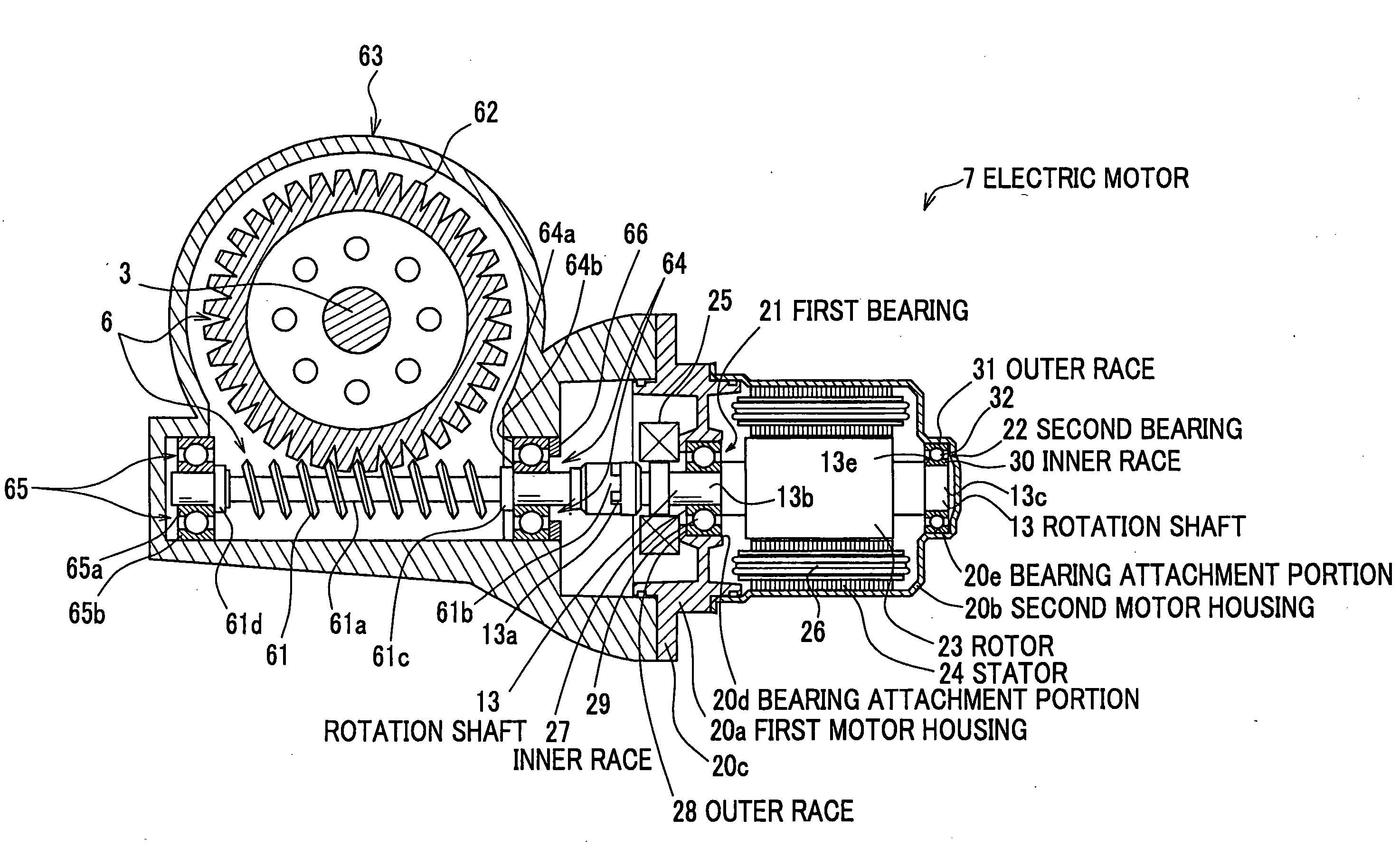
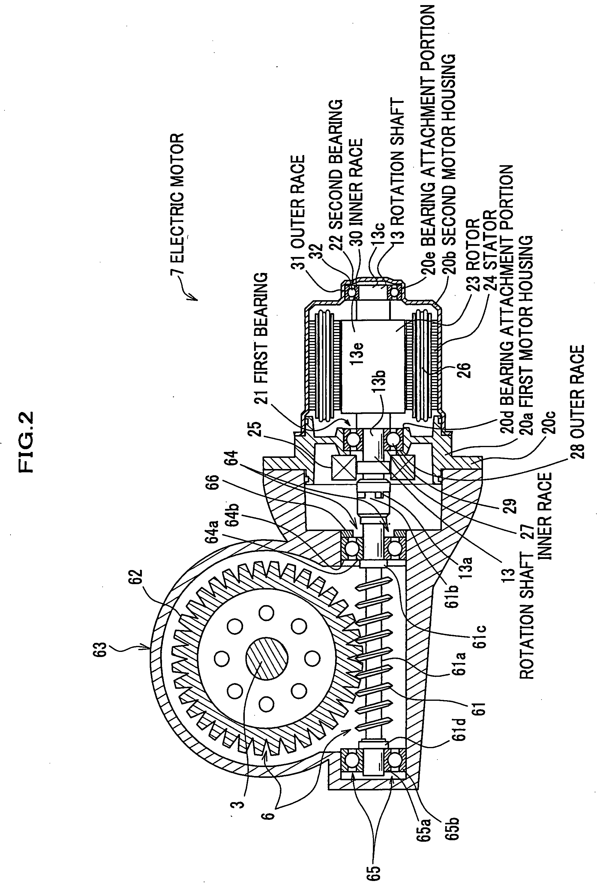
[0054]As seen in FIG. 2, the reduction gear mechanism 6 consists of a speed reduction gear and increases and transmits the rotation torque of the electric motor 7 to the steering shaft 3. The reduction gea...

Example

Second Embodiment

[0072]An electric motor of an electric power steering apparatus according to the second embodiment of the present invention will be described below. Like parts with the same functions as those previously described with reference to the electric motor of the electric power steering apparatus according to the first embodiment as shown in FIG. 3 are denoted by the same reference numerals, and detailed description thereof will be omitted.

[0073]As shown in FIG. 4, an electric motor 7a according to this preferred embodiment is configured such that the outer races 28, 31 of the first and second bearings 21, 22 are respectively press fitted into the inner peripheral surfaces of the corresponding bearing attachment portions 20d, 20e through a plurality (two in the figure) of ring-shaped elastic members 33a, 33b, 34a, 34b.

[0074]In the outer peripheral surfaces of the outer races 28, 31 are formed grooves for the press fitting engagement of the ring-shaped elastic members 33a...

Example

Third Embodiment

[0078]An electric motor of an electric power steering apparatus according to the third embodiment of the present invention will be described below. Like parts with the same functions as those previously described with reference to the electric motor of the electric power steering apparatus according to the second embodiment as shown in FIG. 4 are denoted by the same reference numerals, and detailed description thereof will be omitted.

[0079]As seen in FIG. 5, an electric motor 7b according to this preferred embodiment is configured such that when compared with the second embodiment, the inner race 27 and the outer race 28 of the first bearing 21 are offset in the axial direction of the rotation shaft 13 with respect to the raceway surfaces of the rolling elements 29, 29, and the inner race 30 and the outer race 31 of the second bearing 22 are offset in the axial direction of the rotation shaft 13 with respect to the raceway surfaces of the rolling elements 32, 32, so ...


PUM


Abstract

An electric motor having a rotation shaft includes a motor housing into which the electric motor is accommodated, at least one pair of rolling bearings positioned in the motor housing and rotatably supporting both ends of the rotation shaft, and a displacement restriction member provided inside the motor housing and restricting a displacement of the rolling bearing in an axial direction of the rolling bearing. Each rolling bearing includes an inner race, an outer race, and rolling elements rotatably supported between the inner race and the outer race. The inner race is press fitted without any gaps onto an outer peripheral surface of the rotation shaft, and the outer race is press fitted without any gaps into a bearing attachment portion provided inside the motor housing.

Description

CROSS REFERENCE TO RELATED APPLICATIONS[0001]This application claims the foreign priority benefit under Title 35, United States Code, §119(a)-(d) of Japanese Patent Application No. 2006-058859 filed on Mar. 6, 2006 in the Japan Patent Office, the disclosure of which is herein incorporated by reference in its entirety.BACKGROUND OF THE INVENTION[0002]The present invention relates to an electric motor such as a brushless DC motor, and an electric power steering apparatus employing this electric motor as a drive source.[0003]As a power steering apparatus for easing steering effort of the driver, an electric power steering apparatus using power of an electric motor has been widely adopted for various vehicles in recent years in place of the conventional hydraulic power steering apparatus. In general, an electric power steering apparatus assists the steering operation of the driver by way of reducing the rotation speed of the electric motor and increasing the rotation torque instead by t...

Claims


Application Information

Patent Timeline
IPC IPC(8): H02K7/10H02K5/16
CPCF16C35/067H02K5/1732Y10T74/19828H02K7/1166H02K29/12H02K7/081F16C2380/27B62D5/04F16C35/06F16C35/063H02K7/08
Inventor MIYOSHI, TAKASHISHIMIZU, YASUOYONEDA, ATSUHIKOSAITO, KATSUHIROTOYOFUKU, RYOJIWATANABE, KATSUJI
Owner HONDA MOTOR CO LTD
Why Eureka
Try Eureka