Al technical title is built by PatSnap Al team. It summarizes the technical point description of the patent document.
a technology of inserting sutures and anchors, which is applied in the direction of staples, nails, medical science, etc., can solve the problems of suture being exposed to abrasion or cutting, and achieve the effect of preventing suture abrasion
Inactive Publication Date: 2007-09-27
BENAVITZ WILLIAM C +2
View PDF29 Cites 32 Cited by
Summary
Abstract
Description
Claims
Application Information
AI Technical Summary
This helps you quickly interpret patents by identifying the three key elements:
Problems solved by technology
Method used
Benefits of technology
[0010] At least one length of the insert-molded suture extends from the proximal end of the suture anchor body. Both the suture anchor and suture preferably are made with biodegradable materials. According to one embodiment, irregularities are formed along the surface of the suture, especially where it is molded inside the suture body, to increase pullout strength of the suture from the anchor body. The surface irregularities can be formed by various methods including incorporating a thick fiber into the weave of the suture or by tying knots in the suture.
[0012] The insert-molded suture preferably extends through the entire length of the anchor and exits at the proximal end of the anchor. In a preferred embodiment of the invention, the suture forms a loop outside the proximal end of the anchor. Advantageously, the suture exits the suture anchor along the central axis of the anchor, which prevents suture abrasion by the wall of the bone tunnel into which the anchor is inserted.
Problems solved by technology
Problems can arise if the structure for attaching the suture fails, allowing the suture to become detached from the anchor.
Also, in some of the known devices, the suture is exposed to abrasion or cutting by sharp or rough areas along the walls of the bone canal into which the anchor is inserted.
Method used
Image
Click on the blue label to locate the original text in one second.
Reading with bidirectional positioning of images and text.
Examples
Embodiment Construction
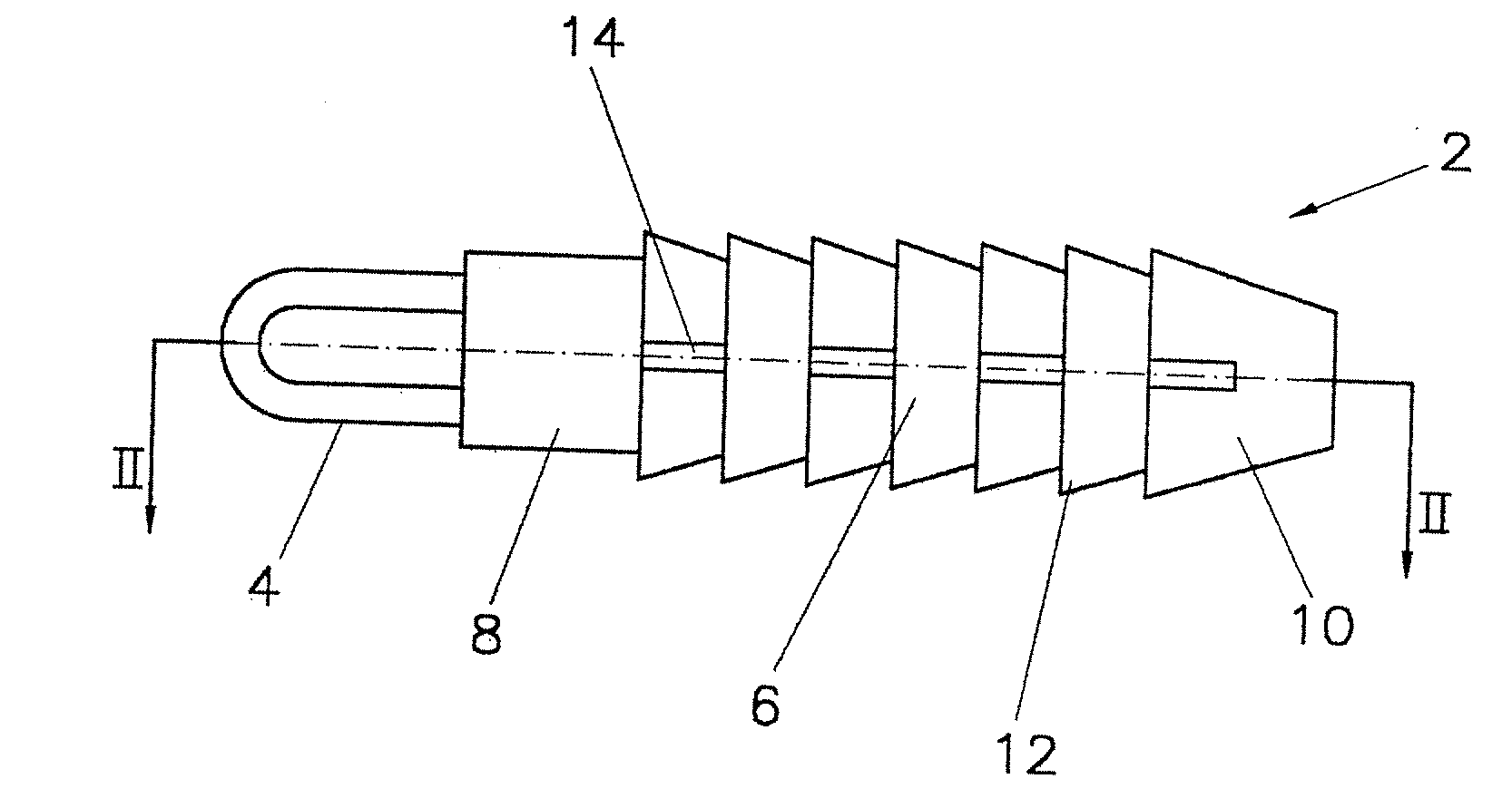
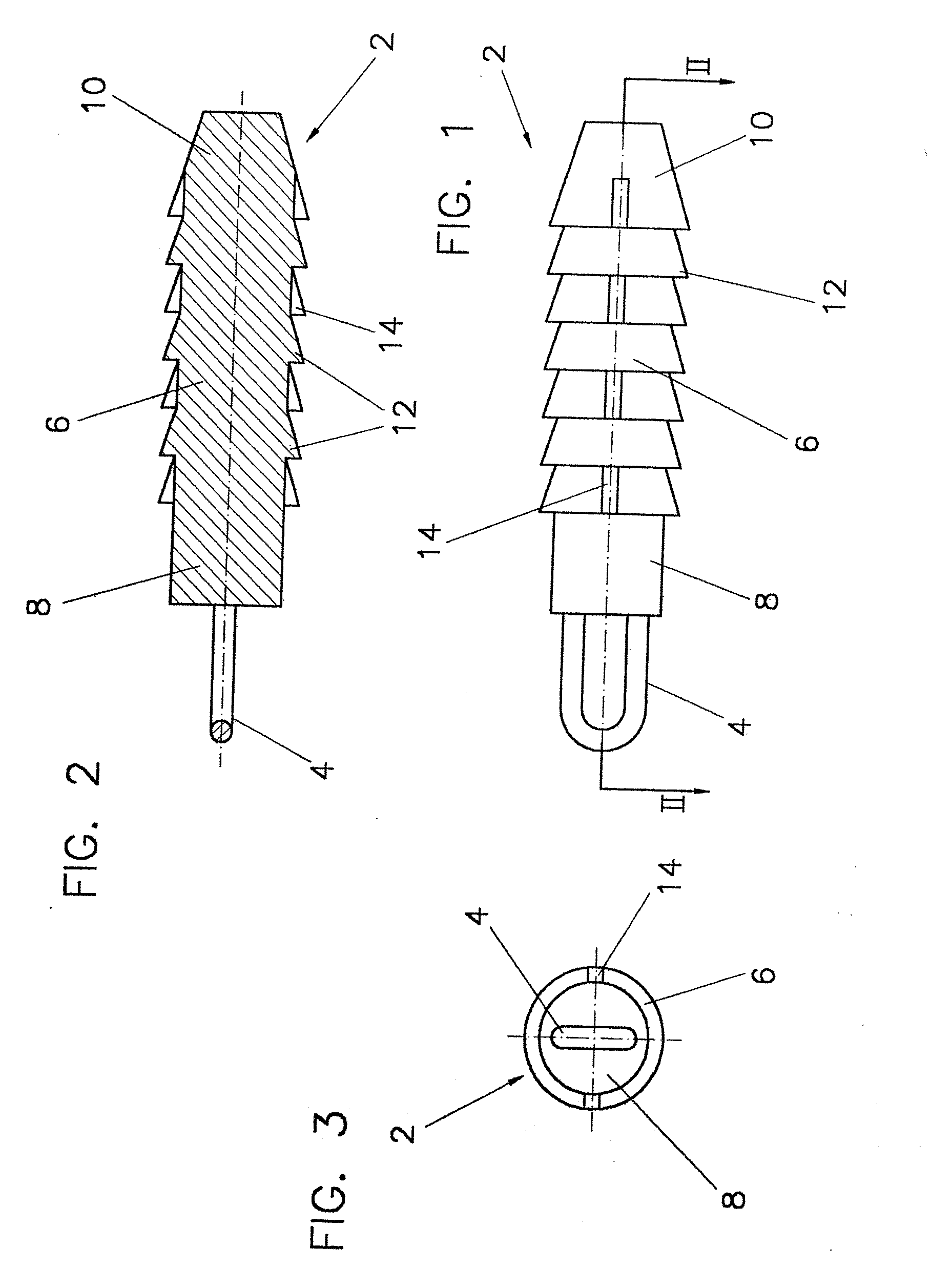
[0025] Referring to FIGS. 1-3, the present invention is shown as a suture anchor 2 having suture 4 that is insert-molded directly into the suture anchor body 6 during the manufacturing process.
[0026] The suture anchor body 6 preferably is formed of a bioabsorbable material, poly(l-lactide-co-d,l-lactide) 70:30 (PLDLA) being most preferred. Suture 4 can be any known type of suture selected according to the size of the anchor and the anticipated application. The suture 4 preferably is No. 2 polyester braided suture.
[0027] At least one length of the insert-molded suture 4 extends from the proximal end of the suture anchor body. Preferably, the suture extends from the suture anchor body in the form of a loop. Various methods of increasing the pull out strength of the suture from the anchor body are disclosed in U.S. Pat. No. 5,964,783 to Grafton et al. which issued on Oct. 12, 1999 and is assigned to the present applicant, the entire disclosure of which is incorporated herein by refer...
PUM
Abstract
An insert-molded suture anchor has a biodegradable polymer body molded around a loop of suture. A tapered end disposed on the proximal end of the body is received into a recess in the distal end of a hand driver. Anchoring ribs are formed along the remaining length of the anchor. The suture is held securely within the anchor body during the insert molding process. The anchor is produced by placing the suture within an injection mold, and injecting biodegradable polymer into the mold. Using a preferred plication driver, the suture anchor can be utilized for capsular plication procedures.
Description
[0001] This is a continuation of U.S. application Ser. No. 10 / 083,568, filed Feb. 27, 2002, now U.S. Pat. No. 7,226,469, which is a continuation-in-part of U.S. application Ser. No. 09 / 495,816, filed Feb. 2, 2000, now U.S. Pat. No. 6,517,564, which claims the benefit of U.S. Provisional Application Ser. No. 60 / 118,228, filed Feb. 2, 1999 and U.S. Provisional Application Ser. No. 60 / 125,781, filed Mar. 23, 1999, the disclosures of which are incorporated herein by reference. This application also claims the benefit of U.S. Provisional Application Ser. No. 60 / 271,414, filed Feb. 27, 2001.BACKGROUND OF THE INVENTION [0002] 1. Field of the Invention [0003] The present invention relates to an apparatus and method for anchoring surgical suture to bone. More specifically, the present invention relates to arthroscopic apparatus and methods for anchoring suture to bone using a suture anchor having suture molded directly into the body of the suture anchor. [0004] 2. Description of the Related ...
Claims
Application Information
Patent Timeline
Application Date:The date an application was filed.
Publication Date:The date a patent or application was officially published.
First Publication Date:The earliest publication date of a patent with the same application number.
Issue Date:Publication date of the patent grant document.
PCT Entry Date:The Entry date of PCT National Phase.
Estimated Expiry Date:The statutory expiry date of a patent right according to the Patent Law, and it is the longest term of protection that the patent right can achieve without the termination of the patent right due to other reasons(Term extension factor has been taken into account ).
Invalid Date:Actual expiry date is based on effective date or publication date of legal transaction data of invalid patent.
Patent Type & Authority Applications(United States)