Ovalized concrete block-out tube with tear away nailing flange

Active Publication Date: 2005-03-03
THOMPSON HARRY A
View PDF12 Cites 19 Cited by
  • Summary
  • Abstract
  • Description
  • Claims
  • Application Information

AI Technical Summary

Benefits of technology

[0012] The tube of the present invention is intended to be cast vertically into the top side of a lower concrete panel with the covered flanged end facing upwardly and the elongate body with the rounded tip embedded in the panel. Once the concrete has set, the ovalized (or non-cylindrical) cross-section of the tube keeps it secure from rotating in the concrete panel and the corrugations along the length of the tube give it high pullout strength. Because of the gentle corrugations formed by the large radius undulations in the walls of the tube, as well as the rounded tube tip, no significant stress concentrations are introduced into the concrete panel by the presence of the tube.
[0013] For joining the lower concrete panel to an upper concrete panel having structural rods extending downwardly from the lower side thereof, the tubes are filled with grout or mortar and the upper panel is lowered onto the lower panel with the structural rods becoming embedded in the grout within the internal cavities of the tubes. The ovalized shape and corrugated walls of the tube provide structural strength to prevent the grout from rotating or pulling out from within the

Problems solved by technology

It is difficult to secure the spiral tube used in the conventional joint to the forms used for pouring a lower panel.
The taped seal at the inner end of the tube may leak allowing concrete to flow into the interior of the tube during the casting of the lower panel.
The tape and plug seals used to close the tube sections are ineffective and frequently allow water, moisture, and dirt to collect in the tubes prior to the erection of the panels.
If the water in the tube freezes there is a risk that resultant expansion will crack and ruin the panel.
Any debris collected within the tube will degrade the quality of the connection formed by the mortar when the panels are erected.
The sharp corner in the concrete at the bottom of the tube concentrates stress in the cast panel and can lead to cracking of the panel.
In addition, the circular cross-section of the spiral tubes is not much larger in diameter than the structural rods which are mortared therein, and thus do not allow any appreciable tolerance for misalignment of the respective connection devices of the two panels.
If there is slight variation in the spacing of th

Method used


Image

  • Ovalized concrete block-out tube with tear away nailing flange
  • Ovalized concrete block-out tube with tear away nailing flange
  • Ovalized concrete block-out tube with tear away nailing flange

Examples


Example

[0025] The following detailed description is of the best presently contemplated mode of carrying out the invention. The description is not intended in a limiting sense, and is made solely for the purpose of illustrating the general principles of the invention. The various features and advantages of the present invention may be more readily understood with reference to the following detailed description taken in conjunction with the accompanying drawings.

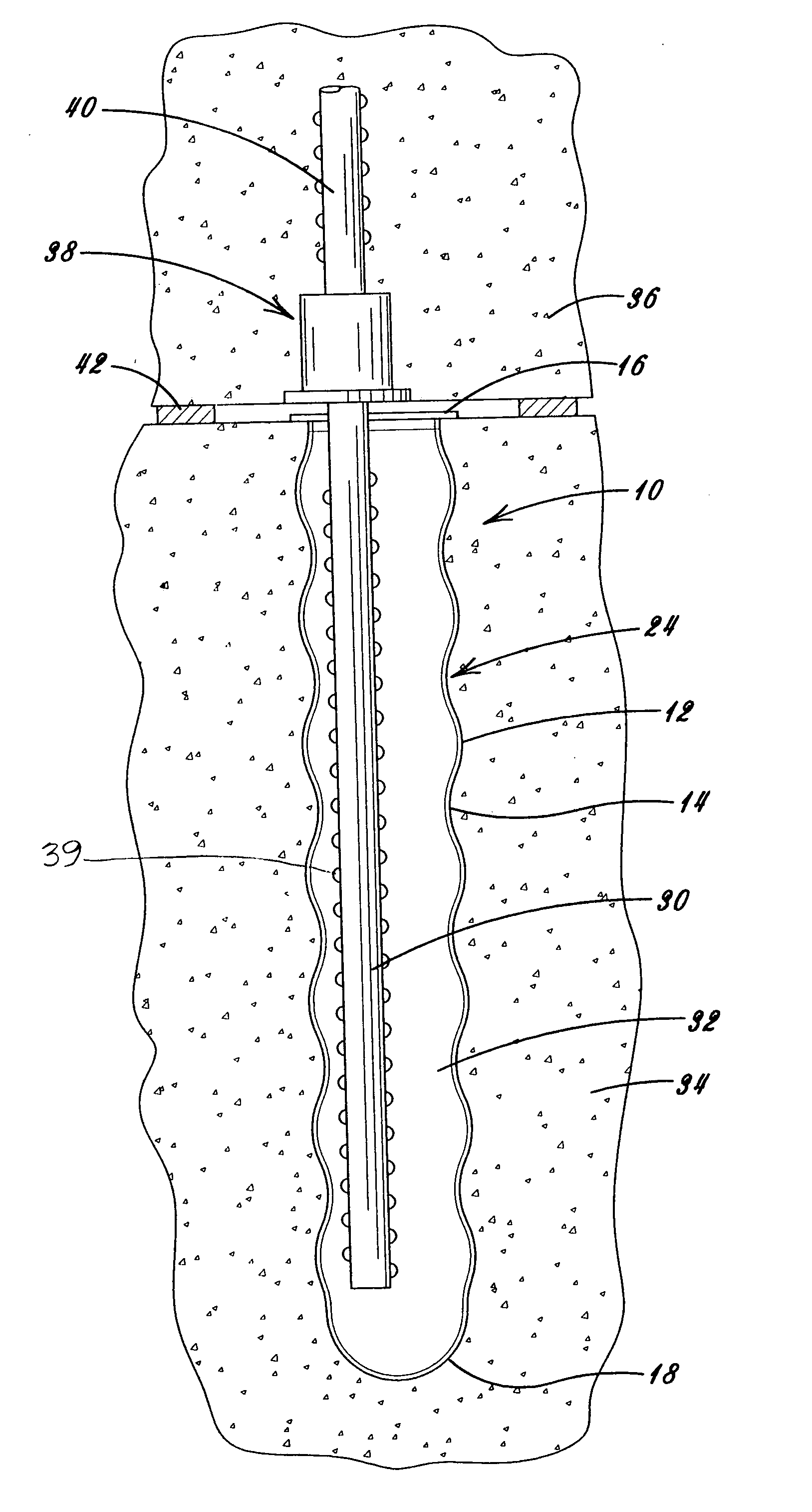
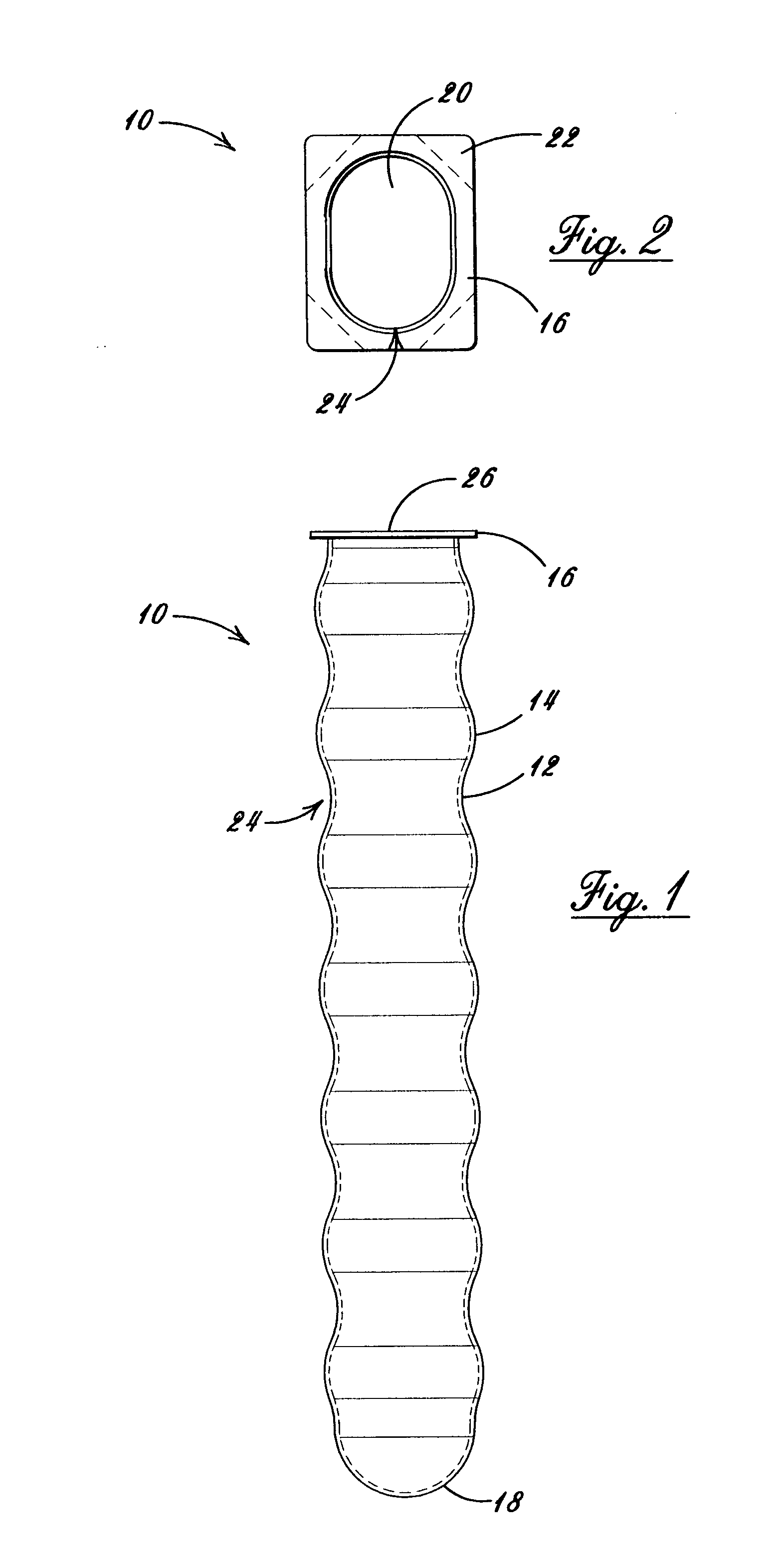
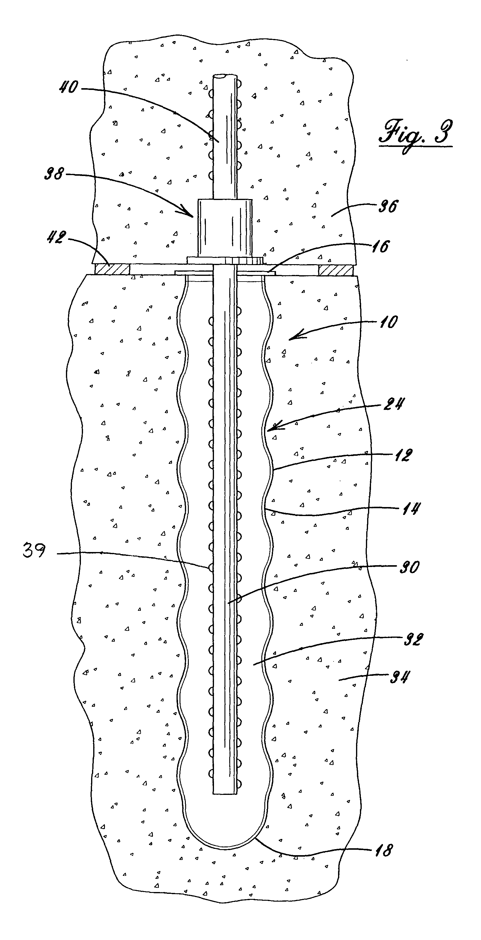
[0026] Referring now to the drawings in detail, where like numerals refer to like parts or elements, there is shown in FIG. 1 a side view of the ovalized (or non-cylindrical) block-out tube 10. The tube 10 is comprised of a rigid corrugated ovalized elongate tubular wall 24 including a series of large-radius circumferential protrusions 14 and large-radius circumferential indentations 12 along the axial orientation thereof. The tube 10 further comprises a closed rounded tip 18 at one end thereof and an open end 26 at the opposite end...


PUM

PropertyMeasurementUnit
Lengthaaaaaaaaaa
Massaaaaaaaaaa
Radiusaaaaaaaaaa

Abstract

A block-out tube for use in joining together pre-cast concrete members, the block-out tube having an ovalized cross-section, an integral elongate imperforate hollow tubular body with smoothly curved corrugated walls, a rounded tip closing the bottom end thereof, a mounting flange with tear-away nail tabs at the top open end thereof, and a removable transparent member for sealing the top end for preventing water and debris from entering the interior of the tube. The block-out tube, secured by attaching the tear-away tabs to a concrete pouring form, is cast into the top of the lower concrete member, the ovalized corrugated body being embedded therein and the top sealed end being exposed at the top surface thereof, after the removal of the form. When the concrete members are erected and joined, the transparent sealing means at the top end is removed, the block-out tube is filled with grout, and a structural rod extending outwardly from one member is fitted into the grout-filled tube as the one member is joined to the other member, the grout engaging the structural rod and the corrugated tube wall, forming a strong joint between the two concrete members.

Description

BACKGROUND OF THE INVENTION [0001] The present invention relates generally to connection devices for joining together pre-cast concrete members such as panels or columns stacked one on top of the other to form building walls, the connection devices employing a grouted connection between a block-out tube cast into the top of a lower concrete member and a structural rod cast into the bottom of an upper concrete member. More particularly, the present invention relates to an ovalized block-out tube that provides structural strength, in addition to a tolerance for misalignment with the structural rod, when the upper panel is assembled onto the lower panel. [0002] Conventional connections for joining cast concrete wall panels use metal spiral tube sections cast into the top of the lower panel. These block-out tube sections are mounted on a framing member in the form used to cast the panel, oriented inwardly in the center of the top wall of the panel. Tape is used to close the bottom of th...

Claims


Application Information

Patent Timeline
IPC IPC(8): B28B7/34B28B23/00E04B1/41E04B1/48E04C5/03E04G15/06
CPCB28B7/342B28B23/0068E04B1/4114Y10T403/57E04C5/03E04G15/061E04B1/48E04B1/483
Inventor THOMPSON, HARRY A.
Owner THOMPSON HARRY A
Why Eureka
Try Eureka