Device and method for automatically assembling heat pipe radiator assembly
What is Al technical title?
Al technical title is built by PatSnap Al team. It summarizes the technical point description of the patent document.
A heat pipe radiator, automatic assembly technology, applied in auxiliary devices, metal processing, metal processing equipment and other directions, can solve the problems of poor quality, low efficiency, low accuracy of manual assembly, etc., to improve production efficiency, reduce labor intensity, improve The effect of assembly accuracy and product quality
Active Publication Date: 2016-11-16
太仓市华盈电子材料有限公司 +1
View PDF7 Cites 18 Cited by
Summary
Abstract
Description
Claims
Application Information
AI Technical Summary
This helps you quickly interpret patents by identifying the three key elements:
Problems solved by technology
Method used
Benefits of technology
Problems solved by technology
[0004] In order to overcome the deficiencies of low manual assembly accuracy, poor quality and low efficiency of existing heat pipe radiator components, the present invention provides a device and method for automatically assembling heat pipe radiator components
Method used
Image
Click on the blue label to locate the original text in one second.
Reading with bidirectional positioning of images and text.
Examples
Embodiment Construction
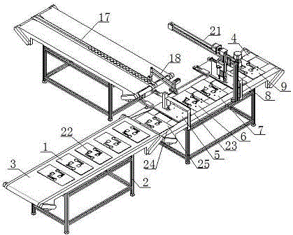
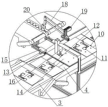
[0024] Such as figure 1 It is a structural schematic diagram of the present invention, figure 2 It is a partially enlarged view of the present invention, a device for automatically assembling heat pipe radiator components, including a tool 1, a frame 2, a feeding conveyor belt 3 and an assembly conveyor belt 4, and the feeding conveyor belt 3 and the assembly conveyor belt 4 are respectively located on the frame 2 The front and rear ends of the assembly conveyor belt 4 are arranged sequentially from front to back with the buffer station 25 with the tool in-position sensor 12 and the heat transfer connection with the positioning gear pin 10, the elastic positioning taper pin 11 and the tool in-position sensor 12. Work station 5, cooling fin station 6, gluing station 7, heat pipe station 8 and upper cover station 9, heat transfer connector station 5 and heat pipe station 8 are also provided with a material box 13 and a guide hole Plate 14, material pushing cylinder 15 and pres...
PUM
Abstract
The invention relates to the technical field of cooling assembly assembling, in particular to a device and method for automatically assembling a heat pipe radiator assembly. The device comprises a jig, a rack, a feeding conveying belt and an assembling conveying belt; the feeding conveying belt and the assembling conveying belt are located at the front end and the rear end of the rack correspondingly; and a buffering station provided with a jig in-place sensor, a heat transfer connection piece station, a cooling fin station, a glue coating station, a heat pipe station and an upper cover station are sequentially arrayed on the assembling conveying belt from front to back, wherein the heat transfer connection piece station, the cooling fin station, the glue coating station, the heat pipe station and the upper cover station are each provided with a positioning gear pin, an elastic positioning taper pin and a jig in-place sensor. The corresponding method includes the following steps of customization of the jig, feeding, assembling and combining, wherein the assembling step includes heat transfer connection piece placement, cooling fin placement, glue coating, heat pipe placement and covering and closing. The method that corresponding parts are positioned, placed and spliced step by step is adopted, automation and process operation of continuous assembling are achieved, the production efficiency is greatly improved, the assembling precision and the product quality are improved, and the labor intensity of workers is reduced.
Description
technical field [0001] The invention relates to the technical field of heat dissipation component assembly, in particular to a device and method for automatically assembling a heat pipe radiator component. Background technique [0002] In computer and other manufacturing industries that require heat pipe radiators to cool integrated blocks, in order to achieve the purpose of transferring heat through heat pipes, it is necessary to connect one end of the heat pipe to the hot end through a heat transfer connector and the other end to a cooling fin with cooling fins. end, to form a heat pipe heat dissipation component, so as to realize the heat on the integrated block to be taken away in time through the heat pipe. [0003] At present, manual methods are used to assemble heat pipe cooling components. First, a tool with heat transfer connectors, heat dissipation fins and heat pipe positioning grooves is made to locate the relative position of the three, which are manually placed...
Claims
Application Information
Patent Timeline
Application Date:The date an application was filed.
Publication Date:The date a patent or application was officially published.
First Publication Date:The earliest publication date of a patent with the same application number.
Issue Date:Publication date of the patent grant document.
PCT Entry Date:The Entry date of PCT National Phase.
Estimated Expiry Date:The statutory expiry date of a patent right according to the Patent Law, and it is the longest term of protection that the patent right can achieve without the termination of the patent right due to other reasons(Term extension factor has been taken into account ).
Invalid Date:Actual expiry date is based on effective date or publication date of legal transaction data of invalid patent.