
Spring contact for an electric connector and connection

A technology of elastic contacts and plug-in devices, which is applied to parts of connection devices, contact parts, coupling devices, etc., can solve the problems of contact burnout, insufficient contact area and contact force, and achieve compact structure and good The effect of contact pressure transmission

Inactive Publication Date: 2009-03-25
ELRAD INT D O O
View PDF0 Cites 17 Cited by
  • Summary
  • Abstract
  • Description
  • Claims
  • Application Information

AI Technical Summary

Problems solved by technology

A difficult problem with the rigid measuring contacts and spring contacts used hitherto is that the two contacts must be aligned exactly with each other in order to establish sufficient electrical contact
However, if the contact pieces or the individual contacts are not aligned with each other, this can lead to burning of the contacts due to vibrations, e.g.

Method used


Image

  • Spring contact for an electric connector and connection
  • Spring contact for an electric connector and connection
  • Spring contact for an electric connector and connection

Examples


Embodiment Construction

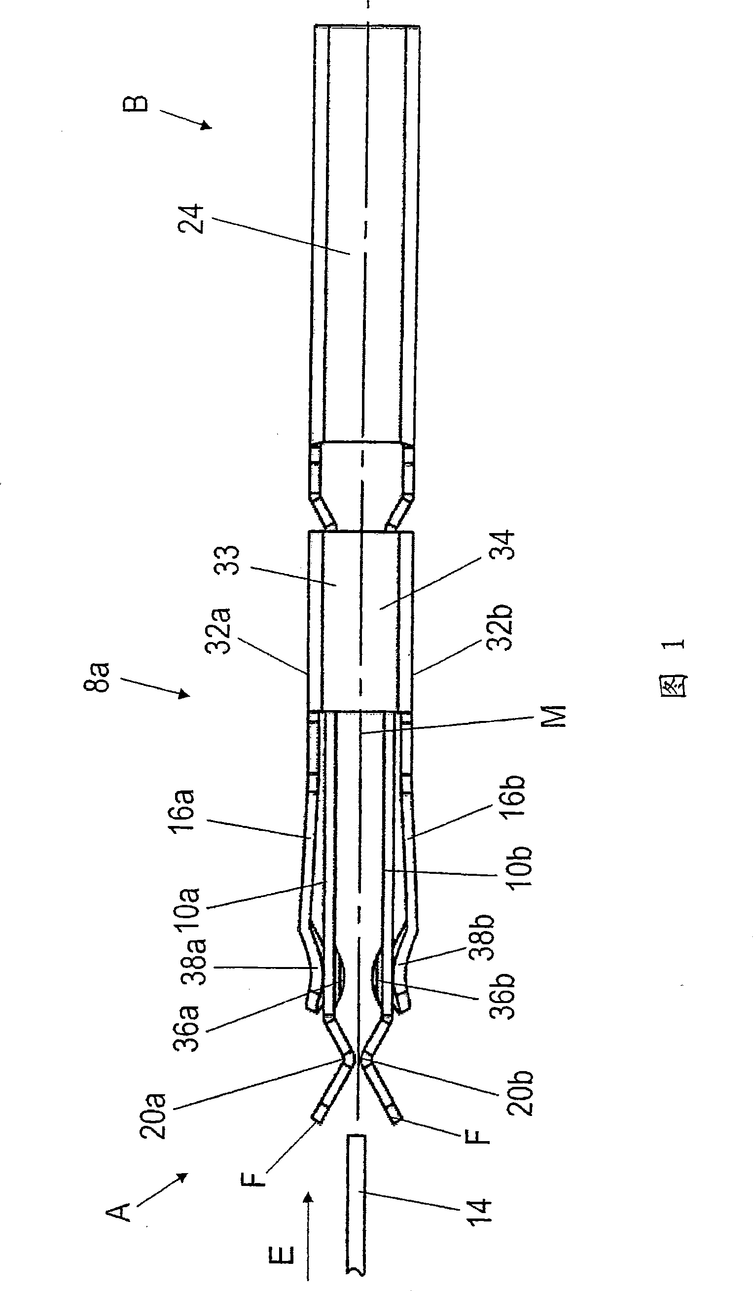
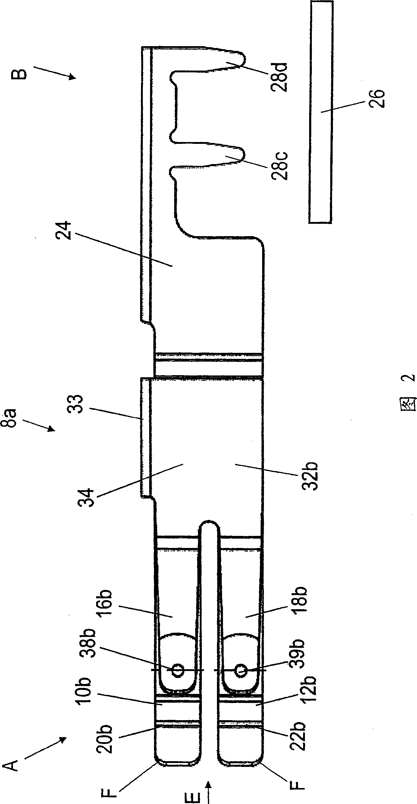
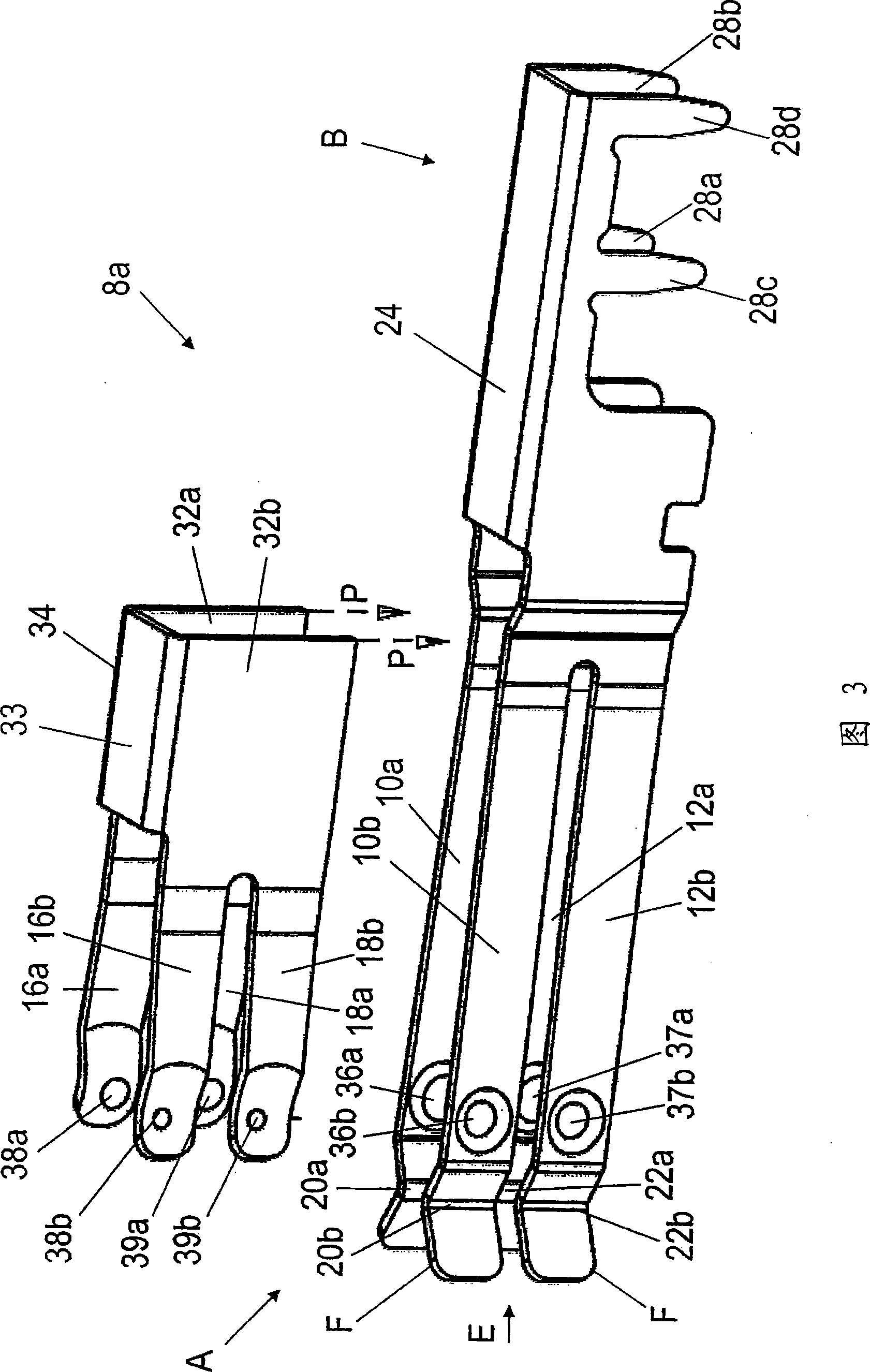
[0030] Figures 1 to 3 schematically show an elastic contact 8a of the electrical plug-in device in different views. Fig. 1 shows a plan view of the elastic contact 8a, Fig. 2 shows a side view, and Fig. 3 shows an exploded perspective view.

[0031] The elastic contact 8a has four elastic contact arms 10a and 10b or 12a and 12b opposite to each other in pairs at the left end A in FIGS. 1 to 3. The corresponding contact 14 shown only schematically in FIG. 1 can be inserted between the opposing contact arm pairs 10a and 10b or 12a and 12b along the insertion direction E of the elastic contact center line M. The corresponding contact 14 is designed as a measuring contact.

[0032] On the outside of the contact arms 10a, 10b, 12a, and 12b facing away from the center line M, a spring arm 16a, 16b, 18a, or 18b is applied, respectively. These spring arms 16a, 16b, 18a, or 18b extend parallel to the corresponding contact arms 10a, 10b, 12a, and 12b. Each of the spring arms 16a, 16b, 18a, ...


PUM


Abstract

A spring contact for an electrical plug connection, which at one end has at least two opposing spring-elastic contact legs for receiving a counterpart contact that can be inserted between the two contact legs in an insertion direction along a central longitudinal axis of the spring contact. The outsides of the contact legs oriented away from the central longitudinal axis are each engaged by respective spring legs which press the respective opposing contact legs toward each other perpendicular to the central longitudinal axis and, when a counterpart contact is inserted, exert a respective contact pressure on the latter. A plug connection equipped with at least one spring contact is also disclosed.

Description

Technical field [0001] The invention relates to an elastic contact of an electrical plug-in device. It has at least two elastic contact arms opposite to each other at one end, which are used to accommodate a corresponding contact. The corresponding contact can be inserted along the center line of the elastic contact. The direction is inserted between the two contact arms. [0002] In addition, the invention also relates to a plug-in device having at least one such elastic contact. Background technique [0003] Such elastic contacts for inserting measuring contacts are known from the prior art. Particularly in battery-operated power tools, such as percussion drills, it is known that the battery or accumulator and the power tool are electrically conductively connected via rigid measuring contacts and elastic contacts. During this period, a number of battery-operated power tools with increasing power were developed, some of which passed peak currents of up to 150 amperes. Based on t...

Claims


Application Information

Patent Timeline
Patent Type & Authority Applications(China)
IPC IPC(8): H01R13/18H01R13/11
CPCH01R12/724H01R9/091H01R13/113H01R13/187H01R12/727H01R12/707
Inventor 弗兰克·斯图克利克
Owner ELRAD INT D O O
Learn More