System for fixing an object in the ground by means of a peg

a technology of object and peg, which is applied in the direction of nails, dowels/piles, bullheads/piles, etc., can solve the problems of insufficient strength of spherical fins, limited effect of barbed hooks, and inability to achieve optimal pull-out strength, etc., to achieve easy placement of anchoring stakes, good pull-out strength, and easy recovery

Inactive Publication Date: 2009-03-03
NICOLET
View PDF30 Cites 23 Cited by
  • Summary
  • Abstract
  • Description
  • Claims
  • Application Information

AI Technical Summary

Benefits of technology

[0008]The invention proposes a system for anchoring an object in the ground using an anchoring stake that offers good pull-out strength, allows easy placement of the anchoring stake, and easy recovery of the latter if it is no longer in use.

Problems solved by technology

Unfortunately, real life has shown that these barbed hooks have a limited effect, especially one that is dependent on the nature of the ground.
Quite often, the ground compacted in the region of the elastic fins as the barbed hook is driven in prevents these fins from returning elastically, which means that the fins offer practically no resistance to the pulling-out of the stake.
This geometry does not have optimum pull-out strength capabilities.
Specifically, if traction is exerted on the stake, the deployable elements have a tendency to yield.
However, the head of the bolt, which projects from the closed head of the tube, is a great impediment to driving the anchoring stake into the ground.
It will be noted that the subsequent operation of placement of the U-shaped anchoring body in the tube is a very tricky one.

Method used


Image

  • System for fixing an object in the ground by means of a peg
  • System for fixing an object in the ground by means of a peg
  • System for fixing an object in the ground by means of a peg

Examples


Embodiment Construction

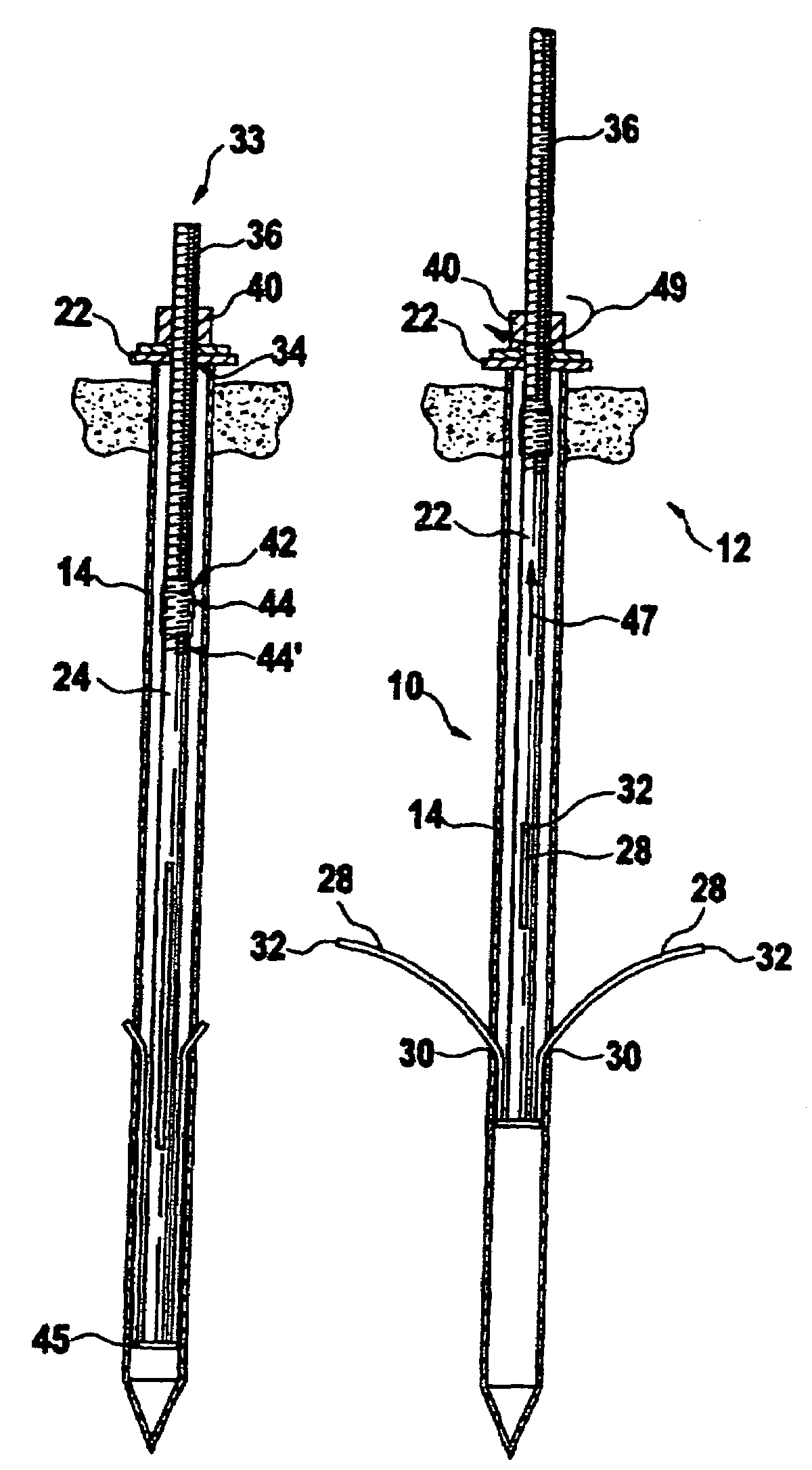
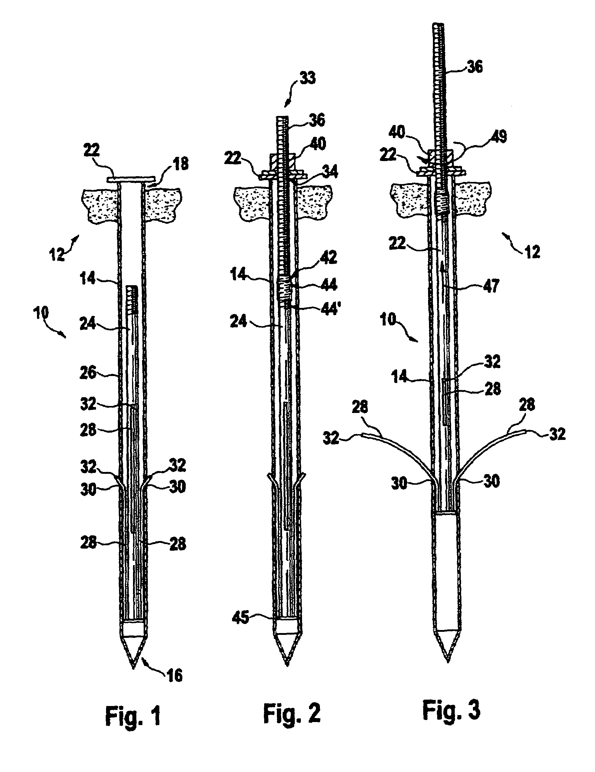
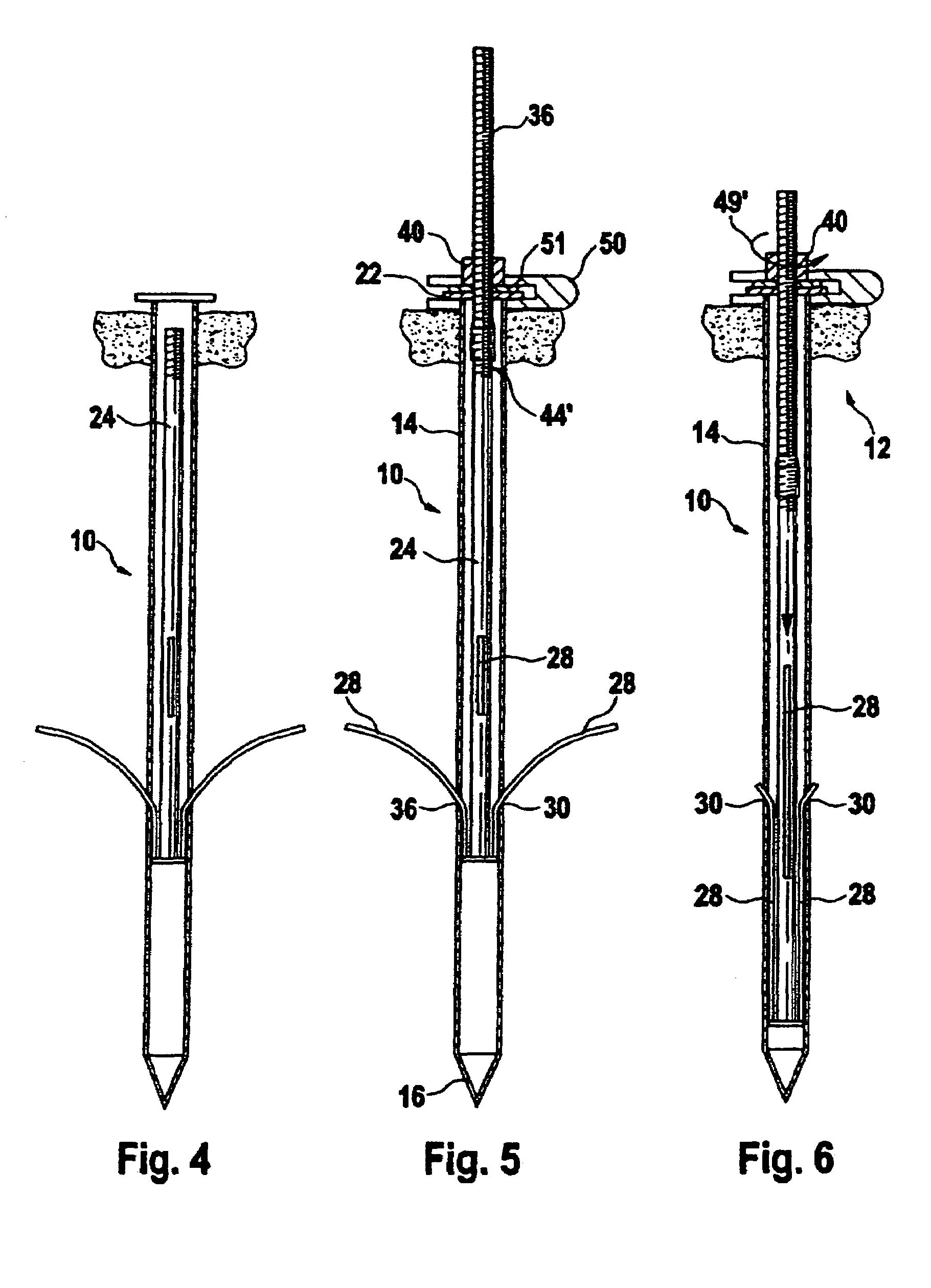
[0037]FIG. 1 illustrates a preferred embodiment of a stake 10 according to the invention, the stake 10 being driven into a medium 12, for example ground. The stake 10 comprises a tube 14 having a spike 16 at a first end and being open at its other end 18. The end 18 of the tube 14 is equipped with a head plate 22 (also known as tube head) forming a collar. As can be seen in FIG. 7, the tube 14 has a square cross section in the embodiment depicted.

[0038]A central support rod 24 is positioned inside the tube 14. This central support rod 24 is equipped with a plurality of anchoring claws 28 secured at their lower part to the central rod 24. As can be seen in FIG. 1, prior to deployment, the claws are arranged along the rod 24. The anchoring claws 28 are preferably made of flexible steel, but may be made of any other material allowing plastic or elastic deformation of the claws without breakage as they deploy.

[0039]The tube 14 comprises, in its side wall 26, a plurality of openings 30. ...


PUM


Abstract

The invention relates to a system for fixing an object in the ground, comprising at least one fixing peg (10) and means for carrying out the above. The peg (10) comprises a tube (14) and at least two lugs (28) on the lower end of a central support rod (24). An axial tension acting on the rod (24) which runs axially in the tube (14) and is fixed in rotation therein, causes the lugs (28) to deploy through openings (30) in the tube (14), such as to cause the extension thereof in the direction of tension at an angle to the length of the tube (14). An operating mechanism (33) comprises a threaded pin (36) with a screw (40) pressing on the head of the tube. The lower end of said threaded pin (36) is coupled to the upper end of the central support (24) in order to transmit an axial tension thereto on turning the screw (40) in a first direction.

Description

TECHNICAL FIELD OF THE INVENTION[0001]The present invention relates to a system for anchoring an object in the ground using a peg or stake, used in particular for anchoring land survey bench-marks such as those used by surveyors, posts of all kinds, particularly fence posts and the post part of signposts.BRIEF DESCRIPTION OF THE RELATED ART[0002]Anchoring stakes for land-survey bench-marks (also known as triangulation pillars) have been known for a very long time in numerous variants. These stakes have to hold bench-marks in the ground for several decades in a way that is reliable in spite of the various kinds of attack that this type of object may experience, such as shifting of the ground, the passage of agricultural vehicles or of livestock. Numerous solutions have already been proposed for increasing the pull-out strength of these stakes. They may be grouped in general into two categories.[0003]The first category of stake uses a fixed-geometry anchoring system. Document U.S. Pat...

Claims


Application Information

Patent Timeline
Patent Type & Authority Patents(United States)
IPC IPC(8): E02D5/74F16B13/06F16B15/00F16M13/00E04H12/22
CPCE02D5/74E02D5/805E04H12/223
Inventor NICOLET
Owner NICOLET
Why Eureka
Try Eureka